Balbharti Maharashtra State Board 12th Physics Important Questions Chapter 12 Electromagnetic Induction Important Questions and Answers.
Maharashtra State Board 12th Physics Important Questions Chapter 12 Electromagnetic Induction
Question 1.
Describe Faraday’s magnet and coil experiment. What conclusion can be drawn from the experiment?
Answer:
Faraday’s magnet and coil experiment:
- The terminals of a copper coil of several turns are connected to a sensitive galvanometer.
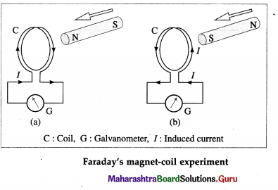
- A bar magnet is moved swiftly towards the coil with its N-pole facing the coil. As long as the magnet is in motion, the galvanometer shows a deflection [from figure (a)].
- If the magnet is now moved swiftly away from the coil, again the galvanometer shows a deflection, but now in the opposite direction.
- The galvanometer shows a deflection when the experiment is repeated with the S-pole of the magnet facing the coil [from figure (b)]. However, the effect of bringing the S-pole towards the coil is the same as that of taking the N-pole away from the coil and vice versa.
- The same results are obtained when the magnet is held still and the coil is moved towards or away from the magnet.
Conclusion : A current is induced in an electric circuit whenever the magnetic flux linked with the circuit keeps on changing as a result of relative motion of a magnet and the circuit.
Question 2.
Describe Faraday’s coil-coil experiment. What conclusion can be drawn from the experiment?
Answer:
Faraday’s coil-coil experiment:
(1) A copper coil P of several turns is connected in series to a rheostat, a tap key and a battery. The terminals of another copper coil Q of several turns are connected to a sensitive galvanometer. The coils are placed close to each other such that when a current is passed through coil P by closing the key K, the magnetic flux through P is linked with coil Q.
(2) On closing the key K, the rise of current in coil P changes the flux linked with the coil Q nearby as shown by a momentary deflection (throw) of the galvanometer G, from below figure. A similar deflection in the same direction is seen if the key closed and either coil is moved swiftly towards the other.
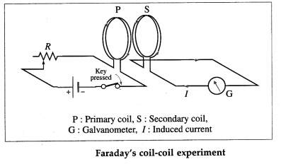
(3) On releasing the tap key, the current in the coil P does not reduce to zero instantaneously. With the decreasing flux through its turns, and a consequent decrease in the flux linked with coil Q, there is an opposite throw of the galvanometer. A similar deflection in the same direction is seen if the key is kept closed and either coil is moved swiftly away from the other.
Conclusion : A current is induced in an electric circuit whenever the magnetic flux linked with the circuit keeps on changing, either as a result of changing current in a nearby circuit or due to relative motion between them.
![]()
Question 3.
Will an induced current be always produced in a coil whenever there is a change of magnetic flux linked with it ?
Answer:
Yes, provided the coil is in a closed circuit.
Question 4.
What is the basis of Lena’s law of electromagnetic Induction?
Answer:
Law of conservation of energy is the basis of Lenz’s law of electromagnetic inductIon.
Question 5.
Express Faraday-Lena’s law of electromagnetic induction in an equation form.
Answer:
Suppose dΦm Is the change in the magnetic flux through a coil or circuit in time dt. Then, by
Faraday’s second law of electromagnetic induction, the magnitude of the einf Induced is
e ∝ \(\frac{d \Phi_{\mathrm{m}}}{d t}\) or e = k\(\frac{d \Phi_{\mathrm{m}}}{d t}\)
where dΦm/dt is the rate of change of magnetic flux
linked with the coil and k is a constant of proportionality. The Sl units of e (the volt) and dΦm df (the weber per second) are so selected that the constant of proportionality, k, becomes unity. Combining Faraday’s law and Lents law of electromagnetic induction, the induced emf
e = – \(\frac{d \Phi_{\mathrm{m}}}{d t}\)
where the minus sign is Included to indicate the polarity of the induced emf as given by Lents law. This polarity simply determines the direction of the induced current in a dosed loop. If a coil has N tightly wound loops, the induced emf will be N times greater than for a single loop, so that
e = – N \(\frac{d \Phi_{\mathrm{m}}}{d t}\)
where \(\frac{d \Phi_{\mathrm{m}}}{d t}\) is the rate of change of magnetic flux through one loop.
Question 6.
State the causes of induced current and explain them on the basis of Lena’s law.
Answer:
According to Lena’s law, the direction of the induced emf or current is such as to oppose the change that produces it. The change that induces a current may be
(i) the motion of a conductor in a magnetic field or
(ii) the change of the magnetic flux through a stationary circuit.
In the first case, the direction of induced emf in the moving conductor Is such that the direction of the side-thrust exerted on the conductor by the magnetic field is opposite in direction to its motion. The motion of the conductor is, therefore, opposed.
In the second case, the induced current sets up a magnetic field of its own which within the area bounded by the circuit is (a) opposite to the original magnetic field if this field is increasing, but (b) is in the same direction as the original field, if the field is decreasing. Thus, it is the change in magnetic flux through the circuit (not the flux itself) which is opposed by the induced current.
![]()
Question 7.
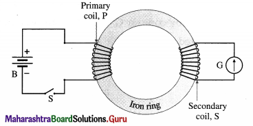
In one version of Faraday’s coil-coil experiment, the two coils are wound on the same iron ring as shown, where closing and opening the switch induces a current in the other coil. How do the multiple-loop coils and iron ring enhance the observation of induced emf?
Answer:
The magnetic flux through a coil is directly proportional to the number of turns a coil has. Hence, with multiloop coils in Faraday’s coil-coil experiment, the induced emf is directly proportional to N. Also, the permeability of iron being many orders of magnitude greater than air, the magnetic field lines of the primary coil P are confined to the iron ring and almost all the flux is linked with the secondary coil S. Thus, increased flux and better flux linkage enhances the magnitude of the induced emf.
Question 8.
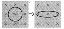
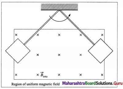
A circular conducting loop in a uniform magnetic field is stretched to an elongated ellipse as shown below. The magnetic field points into the page. Will an emf be induced in the loop? If so, state why and give the direction of the induced current.
Answer:
Looking in the direction of the magnetic field, there will be an induced current in the clockwise sense.
For the same perimeter, the area of a circle is greater than that of an ellipse. Hence, stretching the loop reduces the inward flux through its plane. To oppose this decreasing flux, a current is induced in the clockwise sense so that the field due to the induced current is into the plane of the diagram.
Question 9.
A bar magnet is dropped vertically through a thick copper ring as shown. What is the direction of the force exerted by the coil on the magnet? Explain.
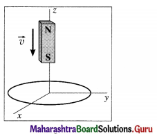
Answer:
The magnetic flux through the loop increases when the magnet approaches the loop, and decreases after the magnet has passed through. The induced current in the loop opposes the cause producing the change in flux which, in this case, is the falling magnet. Therefore, the motion of the magnet’ is opposed, first with a repulsion and then with an attraction. The force, in both cases, is upward in the + z-direction.
The magnetic dipole moment of the falling magnet is directed up. Therefore, looking down the z-axis, the induced current is clockwise when the magnet is approaching the loop, so that the magnetic moment of the loop points down; subsequently, as the magnet recedes, the induced current is anticlockwise.
Question 10.
Briefly explain the jumping ring experiment.
Answer:
Elihu Thompson’s jumping ring experiment is an outstanding demonstration of Faraday’s laws and Lenz’s law of electromagnetic induction. The apparatus consists of a cylindrical laminated iron- cored solenoid. A conducting non-magnetic ring, usually copper or aluminium, is placed over the extended vertical core of the solenoid. When an alternating current is passed through the solenoid, the ring is thrown off high into the air.
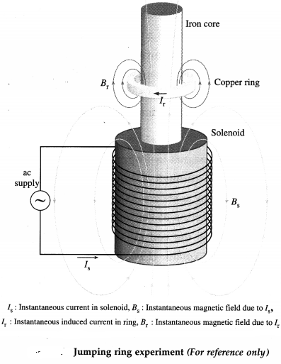
Due to ac, the magnetic field of the solenoid changes continuously. This induces eddy current in the ring. By Lenz’s law, the magnetic field produced by the induced eddy current in the ring opposes the changing magnetic field of the solenoid. Consequently, the two magnetic fields repel each other, making the ring jump.
The iron core increases the magnetic field of the solenoid. Often, the ring is cooled with liquid nitrogen. The colder the ring, the less is its resistance and greater the eddy current in it. More current means a greater magnetic field and even higher jumps.
![]()
Question 11.
Explain what you understand by magnetic flux.
Answer:
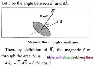
The total number of magnetic lines of force passing normally through a given area in a magnetic field, is called the magnetic flux through that area.
Consider a very small area dA in a uniform magnetic field of induction \(\vec{B}\). The area dA can be represented by a vector \(\overrightarrow{d A}\) perpendicular to it.
[Note : The area vector is perpendicular to the sur-face, so it can point either up and to the right as shown or down and to the left. Although either choice is acceptable, choosing the direction that is closest to the magnetic field is convenient and usually the one we choose.]
Question 12.
How do you find the magnetic flux through a finite area A ?
Answer:
Consider a small area element \(\overrightarrow{d A}\) of a finite area A bounded by contour C, from below figure. Suppose this area is situated in a magnetic field \(\vec{B}\).
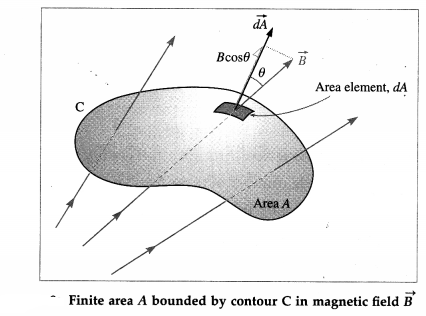
In general, the magnetic field may not be uniform over the area A. Then, the magnetic flux through the area element is dΦm = \(\vec{B} \cdot \overrightarrow{d A}\) = B (dA) cos θ
where θ is the angle between \(\vec{B}\) and \(\overrightarrow{d A}\), so that the flux through the area A is
Φm = \(\int d \Phi_{\mathrm{m}}=\int_{A} \vec{B} \cdot \overrightarrow{d A}=\int_{A}\) B(dA)cos θ
The integration is over the entire area A. \(\vec{B}\) can be taken out of the integral if and. only if \(\vec{B}\) is the same everywhere over A, in which case,
Φm = \(\int_{A}\) B (dA) cos θ = B cos θ \(\int_{A}\) dA = BA cos θ
where \(\int_{A}\) dA is just the total area A.
Question 13.
State an expression for the magnetic flux through a loop of finite area A inside a uniform magnetic field \(\vec{B}\). Hence discuss Faraday’s second law, given that the magnetic flux varies with time.
Answer:
Consider a conducting loop of finite area A, situated in a uniform magnetic field \(\vec{B}\). We choose the direction of the area vector \(\vec{A}\) that is closest to the magnetic field. For the area vector in below figure, the fingers of the right hand must be turned in the sense of the arrow on the contour of the loop.
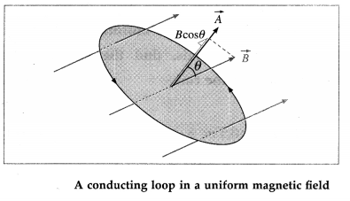
Since \(\vec{B}\) is the same everywhere over A, the flux through the area A is
Φm = BA cos θ
where θ is the angle between \(\vec{B}\) and \(\vec{A}\).
Faraday’s discovery was that the rate of change of flux dΦm/ dt is related to the work done on taking a unit positive charge around the contour in the reverse direction. This work done is just the induced emf. Accordingly we express Faraday’s second law of electromagnetic induction as
|e| = \(\frac{d \Phi_{\mathrm{m}}}{d t}=\frac{d}{d t}\) (BA cos θ)
If B, A and θ are all constants in time, no emf is induced in the loop. An emf will be induced if at least one of these parameters changes with time. B and A may change in magnitude; the loop may turn, thereby changing θ.
![]()
Question 14.
When is the magnetic flux through an area element (i) maximum (ii) zero? Explain.
Answer:
When an area element dA is placed in a magnetic field \(\vec{B}\), the magnetic flux through the element is
dΦm = B(dA) cos θ …………. (1)
where 8 is the angle between \(\vec{B}\) and the area vector \(\overrightarrow{d A}\).
(i) The maximum value of cos θ = 1 when θ = 0. Thus, from Eq. (1), the magnetic flux is maximum, dΦm = B(dA), when the magnetic induction is in the direction of the area vector.
(ii) The minimum value of cos θ = 0 when θ = 90°. Then, the magnetic flux is minimum, dΦm = 0, when the magnetic induction is perpendicular to the area vector.
Question 15.
State the SI units and dimensions of
(i) magnetic induction
(ii) magnetic flux.
Answer:
(i) Magnetic induction, B :
SI unit : the tesla (T) : 1 T = 1 Wb / m2
Dimensions: [B] = [MT-2I-1].
(ii) Magnetic flux, Φm:
SI unit : the weber (Wb)
Dimensions : [Φm] = [B][A]
= [MT-2I-1][L2] = [ML2T-2I-1]
Question 16.
State the relation between the SI units volt and weber.
Answer:
1 volt = 1 weber per second (1 V = 1 Wb/s).
Question 17.
Explain how Lenz’s law is incorporated into Faraday’s second law of electromagnetic induction by introducing a minus sign.
Answer:
Consider a conducting loop of area A in a uniform external magnetic field \(\vec{B}\) with its plane perpendicular to the field, i.e., its area vector \(\vec{A}\) is parallel to \(\vec{B}\) , from below figure. We choose the x-axis along \(\vec{B}\), so that \(\vec{B}=B \hat{i}\) and \(\vec{A}=A \hat{i}\).
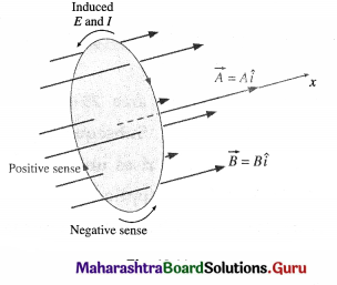
Suppose the magnitude of the magnetic induction increases with time. Then, \(\vec{A}\) remaining constant, the induced emf by Faraday-Lenz’s second law of electromagnetic induction is
e = \(-\frac{d \Phi_{\mathrm{m}}}{d t}=-\frac{d}{d t}(B A)=-A \frac{d B}{d t}\) ………….. (1)
Since we have assumed that B is increasing with time, dB / dt is a positive quantity. Also, A = |\(\vec{A}\)| is positive by definition. Hence, the right hand side of Eq. (1) is a negative quantity.
The right hand rule for area vector fixes the positive sense of circulation around the loop as the clockwise sense. Then, by Lenz’s law the induced current in the loop is in the anticlockwise sense. The sense of the induced emf is the same as the sense of the current it drives. With the clockwise sense fixed as positive, the anticlockwise sense of the induced current is negative. Hence, the sense of e is also negative. That is, the left hand side of Eq. (1) is indeed a negative quantity. Thus, introducing a minus sign in Faraday’s second law incorporates Ienz’s law into Faraday’s law.
18. Solve the following
Question 1.
A coil of effective area 25 m2 is placed in a field-free region. Subsequently, a uniform magnetic field that rises uniformly from zero to 1.25 T in 0.15 s is applied perpendicular to the plane of the coil. What is the magnitude of the emf induced in the coil?
Solution:
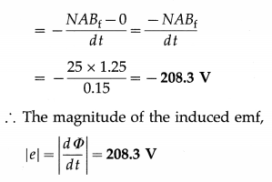
Data : NA = 25 m2, Bf = 1.25 T, Bi = 0, A t = 0.15 s
Initial magnetic flux, Φi = 0 (∵ Bi = 0)
Final magnetic flux, Φf = NABf
e = –\(\frac{d \Phi}{d t}=-\frac{\left(\Phi_{\mathrm{f}}-\Phi_{\mathrm{i}}\right)}{d t}\)
![]()
Question 2.
A rectangular coil of length 0.5 m and breadth 0.4 m has resistance of 5 Ω. The coil is placed in a magnetic field of induction 0.05 T and its direction is perpendicular to the plane of the coil. If the magnetic induction is uniformly reduced to zero in 5 milliseconds, find the emf and current induced in the coil.
Solution:
Data : l =0.5 m, b = 0.4 m, R = 5Ω, B = 0.05 T, Bf = 0, dt = 5 × 10⁻³ s
Area of the coil, A = lb = 0.5 × 0.4 = 0.2 m2
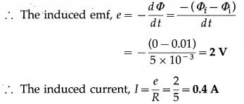
Initial magnetic flux, Φi = ABi
= 0.02 × 0.05 = 0.01 Wb
Final magnetic flux, Φf = 0 (∵ Bf = 0)
Question 3.
A square wire loop with sides 0.5 m is placed with its plane perpendicular to a magnetic field. The resistance of the loop is 5 Ω. Find at what rate the magnetic induction should be changed so that a current of 0.1 A is induced in the loop.
Solution:
Data : l = 0.5 m, R = 5 Ω, I = 0.1 A
A = l2 = 0.5 × 0.5 = 0.25 m2
The magnitude of the induced emf,
|e| = \(\frac{d \Phi}{d t}=\frac{d}{d t}\) (BA) = A \(\frac{d B}{d t}\)
since the area (A) of the coil is constant. The induced current, I = \(\frac{|e|}{R}=\frac{A}{R} \frac{d B}{d t}\)
∴ The time rate of change of magnetic induction,
\(\frac{d B}{d t}=\frac{I R}{A}=\frac{0.1 \times 5}{0.25}\) = 2 T/s
Question 4.
The magnetic flux through a loop of resistance 0.1 Ω is varying according to the relation Φ = 6t2 + 7t + 1, where Φ is in mihiweber and t is in second. What is the emf induced in the loop at t = 1 s and the magnitude of the current?
Solution:
Data: R = 0.1 Ω, Φm = 6t2 + 7t + 1 mWb, t = 1 s
(i) The induced emf, |e| = \(\frac{d \Phi_{\mathrm{m}}}{d t}\) = \(\frac{d}{d t}\)(6t2 + 7t + 1)
= (12t + 7) mV
= 12(1) + 7 = 19 mV
(ii) The magnitude of the current = \(\frac{|e|}{R}\)
= \(\frac{19 \mathrm{mV}}{0.1 \Omega}\) = 190 mA
Question 5.
A wire 88 cm long is bent into a circular loop and kept with its plane perpendicular to a magnetic field of induction 2.5 Wb/m2. Within 0.5 second, the coil is changed to a square and the magnetic induction is increased by 0.5 Wb/m2. Calculate the emf induced in the wire.
Solution:
Data: l = 88 cm, Bi = 2.5 Wb/m2, Bf = 3 Wb/m2, ∆t = 0.5 s
For the circular loop, l = 2πr
∴ r = \(\frac{l}{2 \pi}=\frac{88}{2 \times(22 / 7)}\) = 14 cm = 0.14 m
Area of the circular loop, Ai = πr2
= \(\frac{22}{7}\) (0.14)2 = 0.0616 m2
Initial magnetic flux, Φi = AiBi
= 0.0616 × 2.5 = 0.154 Wb
For the square loop, length of each side
= \(\frac{88}{4}\) cm = 22 cm = 0.22 m 4
Area of the square loop, Af = (0.22)2
= 0.0484 m2
∴ Final magnetic flux, Φf = AfBf
= 0.0484 × 3 = 0.1452 Wb
Induced emf, e = – \(\frac{\Phi_{\mathrm{f}}-\Phi_{1}}{\Delta t}=\frac{\Phi_{1}-\Phi_{\mathrm{f}}}{\Delta t}\)
∴ e = \(\frac{0.154-0.1452}{0.5}\) = 8.8 × 10-3 × 2
= 1.76 × 10⁻² V
![]()
Question 6.
A 1000 turn, 20 cm diameter coil is rotated in the Earth’s magnetic field of strength 5 × 10⁻⁵ T. The plane of the coil was initially perpendicular t0 the Earth’s field and is rotated to be parallel to the field in 10 ms? Find the average emf induced.
Solution:
Data: N = 1000, d = 0.2 m, B = 5 × 10⁻⁵ T,
∆t = 10 ms = 10-2 s
Radius of coil, r = d/2 = 10-1 m
Induced emf, e = -N \(\frac{\Delta \Phi_{\mathrm{m}}}{\Delta t}=-N \frac{\Phi_{\mathrm{f}}-\Phi_{1}}{\Delta t}\)
Initial area, Ai = πr2 and initial flux,
NΦi = NBAi NB (πr2)
Final flux, Φf = 0, since the plane of the coil is parallel to the field lines.
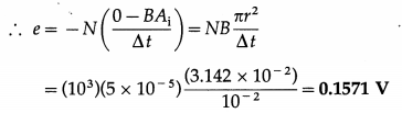
Question 7.
A television loop antenna has diameter of 11 cm. The magnetic field of the TV signal is uniform, normal to the plane of the loop and changing at the rate of 0.16 T/s. What is the magnitude of the emf induced in the antenna?
Solution:
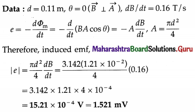
Question 8.
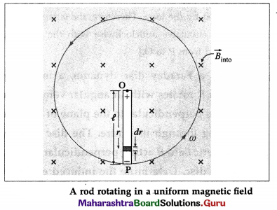
The magnetic field through a wire loop, of radius 12 cm and resistance 8.5 Ω, changes with time as shown in the graph below. The magnetic field is uniform and perpendicular to the plane of the loop. Calculate the emf induced in the loop as a function of time. Hence, find the induced emf in the time interval (a) t = 0 to t = 2 s (b) t = 2 s to t = 4s (c) t = 4s to t = 6s.
Solution :
Data : r = 0.12 m, R = 8.5 Ω
This is the emf induced in the loop as a function of time.
\(\frac{d B}{d t}\) is the slope of the B-t graph
Question 19.
What is motional emf?
Answer:
An emf induced in a conductor or circuit moving in a magnetic field is called motional emf.
Question 20.
Determine the motional emf induced in a straight conductor moving in a uniform magnetic field with constant velocity.
Answer:
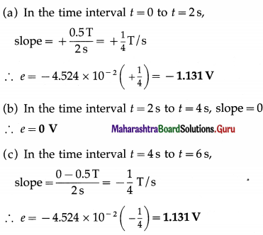
Consider a straight wire AB resting on a pair of conducting rails separated by a distance l lying wholly in a plane perpendicular to a uniform magnetic field \(\vec{B}\). \(\vec{B}\) points into the page and the rails are stationary relative to the field and are connected to a stationary resistor R.
Suppose an external agent moves the rod to the right with a constant speed v, perpendicular to its length and to \(\vec{B}\). As the rod moves through a distance dx = vdt in time dt, the area of the loop ABCD increases by dA = ldx = lv dt.
Therefore, in time dt, the increase in the magnetic flux through the loop,
dΦm = BdA = Blvdt
By Faraday’s law of electromagnetic induction, the magnitude of the induced emf
e = \(\frac{d \Phi_{\mathrm{m}}}{d t}=\frac{B l v d t}{d t}\) = Blv
Question 21.
Determine the motional emf induced in a straight conductor moving in a uniform magnetic field with constant velocity on the basis of Lorentz force.
Answer:
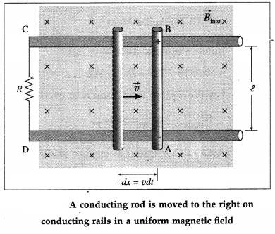
Consider a straight rod or wire PQ of length l, lying wholly in a plane perpendicular to a uniform magnetic field of induction B , as shown in below figure; \(\vec{B}\) points into the page.
Suppose an external agent moves the wire to the right with a constant velocity \(\vec{v}\) perpendicular to its length and to \(\vec{B}\). The free electrons in the wire experience a Lorentz force \(\vec{F}\) ( = q\(\vec{v}\) × \(\vec{B}\)).
According to the right-hand rule for cross products, the Lorentz force on negatively charged electrons is downward. The Lorentz force \(\vec{F}\) moves the free electrons in the wire from P to Q so that P becomes positive with respect to Q. Thus, there will be a separation of the charges to the two ends of the wire until an electric field builds up to oppose further motion of the charges.
In moving the electrons a distance l along the wire, the work done by the Lorentz force is
W = Fl = (qvB sin θ) l = qvBl
since the angle between \(\vec{v}\) and \(\vec{B}\), θ = 90°. Since electrical work done per unit charge is emf, the induced emf in the wire is
e = \(\frac{W}{q}\) = vB l
Alternatively, the electric field due to the separation of charges is \(\vec{F} / q=\vec{v} \times \vec{B}\). Since \(\vec{v}\) is perpendicular to B, the magnitude of the field = vB.
Electric field = \(\frac{\text { p.d. }(e) \text { between } \mathrm{P} \text { and } \mathrm{Q}}{\text { distance } \mathrm{PQ}(l)}\)
Therefore, the p.d. or emf induced in the wire PQ is e = v B l
![]()
Question 22.
Determine the motional emf induced in a straight conductor rotating in a uniform magnetic field with constant angular velocity.
Answer:
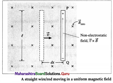
Suppose a rod of length l is rotated anticlockwise, around an axis through one end and perpendicular to its length, in a plane perpendicular to a uniform magnetic field of induction \(\vec{B}\), as shown in below figure; \(\vec{B}\) points into the page. Let the constant angular speed of the rod be ω.
Consider an infinitesimal length element dr at a distance r from the rotation axis. In one rotation, the area traced by the element is dA = 2πrdr. Therefore, the time rate at which the element traces out the area is
\(\frac{d A}{d t}\) = frequency of rotation × dA = f dA
where f = \(\frac{\omega}{2 \pi}\) is the frequency of rotation.
∴ \(\frac{d A}{d t}=\frac{\omega}{2 \pi}\) (2πrdr) = ωr dr
Therefore, the magnitude of the induced emf in the element is
|de| = \(\frac{d \Phi_{\mathrm{m}}}{d t}=B \frac{d A}{d t}\) = B ωr dr
Since the emfs in all the elements of the rod will be in series, the total emf induced across the ends of the rotating rod is
|e| = \(\int d e=\int_{0}^{l} B \omega r d r=B \omega \int_{0}^{l} r d r=B \omega \frac{l^{2}}{2}\)
For anticlockwise rotation in B pointing into the page, the pivot point O\(\vec{B}\) is at a higher potential.
[Note : To understand the polarity of the emf across the ends of the rod, imagine that the rod slides along a wire that forms a circular arc MPN of radius /, as shown below. Assume that the resistor R furnishes all of the resistance in the closed loop. As 9 increases, so does the inward flux through the loop due to \(\vec{B}\).
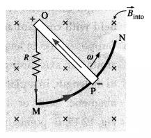
To counteract this increase, the magnetic field due to the induced current must be directed out of the page in the region enclosed by the loop. Therefore, the current in the loop POMP circulates anticlockwise with the motional emf directed from P to O.]
23. Solve the following
Question 1.
A straight metal wire slides to the right at a constant 5 m/s along a pair of parallel metallic rails 25 cm apart. A 10 Ω resistor connects the rails on the left end. The entire setup lies wholly inside a uniform magnetic field of strength 0.5 T, directed into the page. Find the magnitude and direction of the induced current in the circuit.
Solution:
Data : v = 5 m/s, l = 0.25 m, R = 10 Ω, B = 0.5T
The induced current,
i = \(\frac{e}{R}=\frac{B l v}{R}=\frac{(0.5)(0.25)(5)}{10}\) = 0.0625 A
Since the magnetic flux into the page through the | closed conducting loop increases, the induced current in the loop must be anticlockwise. Alternatively, Fleming’s right hand rule gives the direction of induced current in the moving wire from bottom to top.
Question 2.
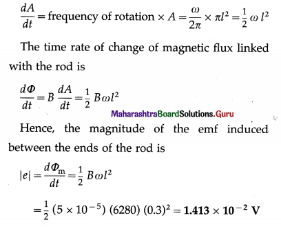
A straight conductor (rod) of length 0.3 m is rotated about one end at a constant 6280 rad/s in a plane normal to a uniform magnetic field of induction 5 × 10⁻⁵ T. Calculate the emf induced between its ends.
Solution:
Data : l = 0.3 m, ω = 6280 rad/s, B = 5 × 10⁻⁵ T In one rotation, the rod traces out a circle of radius l, i.e., an area, A = πl2. Therefore, the time rate at which the rod traces out the area is
Question 3.
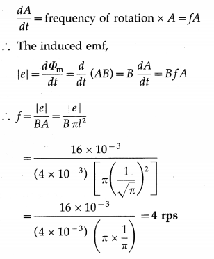
A metal rod 1/\(\sqrt{\pi}\) m long rotates about one of its ends in a plane perpendicular to a magnetic field of induction 4 × 10⁻³ T. Calculate the number of revolutions made by the rod per second if the emf induced between the ends of the rod is 16 m V.
Solution :
Data : r = l = \(\frac{1}{\sqrt{\pi}}\) m, B = 4 × 10⁻³ T, |e| = 16 mV = 16 × 10-3 V
In one rotation, the rod traces out a circle of radius Z, i.e., an area, A = πl2
Therefore, the time rate at which the rod traces out the area is
![]()
Question 4.
A cycle wheel with 10 spokes, each of length 0. 5 m, is moved at a speed of 18 km/h in a plane normal to the Earth’s magnetic induction of 3.6 × 10⁻⁵ T. Calculate the emf induced between
(i) the axle and the rim of the cycle wheel
(ii) ends of a single spoke and ten spokes.
Solution:
Data : r = l = 0.5 m, v = 18 km/h = \(\frac{18000}{3600}\) = 5 m/s,
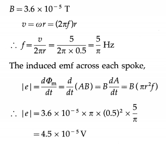
Since the spokes have common ends (the axle and wheel rim), they are connected in parallel. Hence,
the emf induced between the end of a single spoke and the other common end of ten spokes is also 4.5 × 10⁻⁵ V.
Since the total emf of this parallel combination of identical emfs e is equal to a single emf e, the emf induced between the axle and wheel rim is equal to 4.5 × 10⁻⁵ V.
Question 24.
Briefly describe with necessary diagrams the experimental setup to investigate the phenomenon of electromagnetic induction for a magnet swinging through a coil.
Answer:
Apparatus: A permanent magnet is mounted at the centre of the arc of a semicircular aluminium frame of radius 50 cm. The whole frame is pivoted at its centre and can oscillate freely in its plane, from figure (a). Movable weights m1 and m2 on the radial arms of the frame can be symmetrically positioned to adjust the period of oscillation from about 1.5s to 3s. The magnet can freely pass through a copper coil of about 10000 turns.
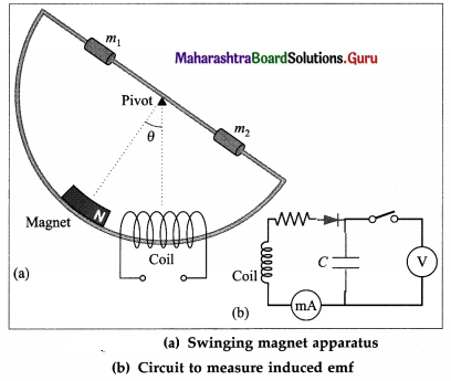
When the magnet swings through and out of the coil, the magnetic flux through the coil changes, inducing an emf. The amplitude of the swing can be read from the graduations on the arc. Since the induced emf will be small, it may be measured by connecting the terminals of the coils to a CRO (cathode-ray oscilloscope, or they may be connected to a 100 pF capacitor through a diode, from figure (b), and the voltage across the capacitor is measured. The resistor in series with the diode helps to adjust the capacitor charging time ( = RC).
[Note : Real-time graphs can be captured using a datalogger connected to a computer. The datalogger uses rotary motion, voltage and magnetic field sensors to measure the angle, the induced voltage and the magnetic flux, respectively.]
Question 25.
In the experiment to investigate the phenomenon of electromagnetic induction for a magnet swinging through a coil, relate the graphical representations (flux-time and voltage-time) with the motion of the magnet.
Answer:
In the demonstration of a magnet swinging through a coil, a voltage is induced in the coil as the magnet swings through it. For the discussion, we assume the length of the magnet to be smaller (about half) than the length of the coil and the North pole of the magnet swings into the coil from the left. (The polarity of the induced voltage pulse depends on the polarity of the magnet.)
We take the magnetic flux linked with the coil to be nearly zero when the magnet is high up away from the coil. As the magnet moves through it the coil and recedes, the magnetic field through the coil increases to its maximum and then decreases. There is a substantial magnetic field at the coil only when it is very near the magnet. Moreover, the speed of the magnet is maximum when it is at the centre of the coil, since it is then at the mean position of its oscillation. Thus the magnetic field changes quite slowly when the magnet is far away and rapidly as it approaches the coil, from figure (a).
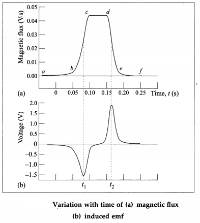
The flux through the coil increases as the north pole approaches the left end of the coil, and reaches a maximum when the magnet is exactly midway in the coil, as shown by the portion be in from figure (a). By Lenz’s law, the induced emf will produce a leftward flux that will seek to oppose the increasing magnetic flux of the magnet through the coil.
The interval cd, when the flux is maximum but remains constant and induced emf is zero, corresponds to the situation where the magnet is wholly inside the coil.
Once the magnet swings past the centre of the coil, the flux through the coil starts to decrease-the interval de. To reinforce the decreasing flux of the magnet through the coil, a rightward flux is now induced, thereby flipping the polarity of the induced emf.
If we use a coil that is shorter than the magnet, the time interval cd for which the induced emf remains zero would have been shorter. The times f1 and f2 in from figure (a) are the points of inflection of the curve, and in from figure (b) are obviously the minimum and maximum of the induced emf, respectively. The sequence of two pulses, one negative and one positive, occurs during just half a cycle. On the return swing of the magnet, they are repeated in the same order.
![]()
Question 26.
In the experiment to investigate the phenomenon of electromagnetic induction for a magnet swinging through a coil, show that the peak induced emf is directly proportional to the speed of the magnet (or show that the peak induced emf is directly proportional to the angular amplitude and inversely proportional to the time period).
Answer:
In the experiment, a magnet is swung through a coil in a radius R. The angular position θ of the magnet is measured from the vertical, the mean position of the swing. The angular amplitude is θ0.
The kinetic energy of the system is \(\frac{1}{2}\) Iω2 and the potential energy (relative to the lowest position of the magnet) is MgR(1 – cos θ), where M is mass of the system. Conservation of energy gives, for small θ,
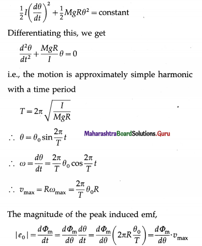
as required. The rate of change of flux through the coil is essentially proportional to the velocity of the magnet as it passes through the coil. By choosing different amplitudes of oscillation of the magnet, we can alter this velocity.
Question 27.
What is an ac generator? State the principle of an ac generator.
Answer:
An electric generator or dynamo converts mechanical energy into electric energy, just the opposite of what an electric motor does.
Principle : An AC generator works on electro-magnetic induction : When a coil of wire rotates between two poles of a permanent magnet such that the magnetic flux through the coil changes periodically with time due to a change in the angle between the area vector and the magnetic field, an alternating emf is induced in the coil causing a current to pass when the circuit is closed.
Question 28.
Briefly describe the construction of a simple ac generator. Obtain an expression for the emf induced in a coil rotating with a uniform angular velocity in a uniform magnetic field. Show graphically the variation of the emf with time (t). OR Describe the construction of a simple ac generator and explain its working.
Answer:
Construction : A simplified diagram of an ac generator is shown in below figure 12.18. It consists of many loops of wire wound on an armature that can rotate in a magnetic field. When the armature is turned by some mechanical means, an emf is generated in the rotating coil.
Consider the coil to have N turns, each of area A, and rotated with a constant angular speed ω – about an axis in the plane of the coil and perpendicular to a uniform magnetic field \(\vec{B}\), as shown in the figure. The frequency of rotation of the coil is f = ω / 2π.
Working : The angle 9 between the magnetic field \(\vec{B}\) and the area of the coil \(\vec{A}\) at any instant t is θ = ωt (assuming θ = 0° at t = 0). At this position, the magnetic flux through the coil is
Φm = \(N \vec{B} \cdot \vec{A}\) = NBA cos θ = NBA cos ωt
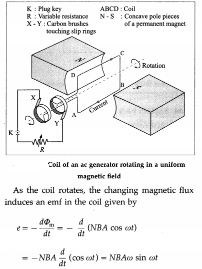
∴ e = e0 sin ωt, where e0 = NBAω.
Therefore the induced emf varies as sin cot and is called sinusoidally alternating emf. In one rotation of the coil, sin cot varies between +1 and – 1 and hence the induced emf varies between +e0 and -e0. The maximum value e0 of an alternating emf is called the peak value or amplitude of the emf.
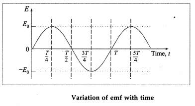
The sinusoidal variation of emf with time t is shown in above figure. The emf changes direction at the end of every half rotation of the coil. The frequency of the alternating emf is equal to the frequency/of rotation of the coil. The period of the alternating emf is T = \(\frac{1}{f}\)
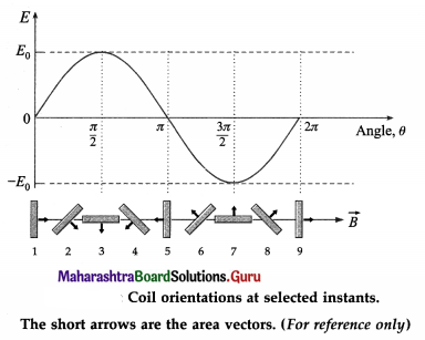
Imagine looking at the coil of the ac generator from the slip rings along the rotation axis in Fig. 12.18. The magnetic flux, rate of change of flux and sign of the induced emf are shown in the table below for the different orientations of the coil as in below figure.
Coil orientation | Flux Φm | dΦm/dt | Induced emf |
| 1 | Positive maximum | Momentarily zero (constant flux) | Zero |
| 2 | Positive | Decreasing (negative) | Positive |
| 3 | Zero | Decreasing (negative) | Positive |
| 4 | Negative | Decreasing (negative) | Positive |
| 5 | Negative maximum | Momentarily zero (constant flux) | Zero |
| 6 | Negative | Increasing (positive) | Negative |
| 7 | Zero | Increasing (positive) | Negative |
| 8 | Positive | Increasing (positive) | Negative |
| 9 | Return to positive maximum | Momentarily zero (constant flux) | Zero |
Question 29.
How does a dc generator differ from an ac generator?
Answer:
A dc generator is much like an ac generator, except that the slip rings at the ouput are replaced by a split-ring commutator, just as in a dc motor.
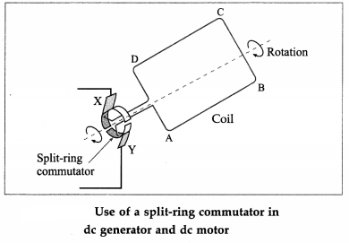
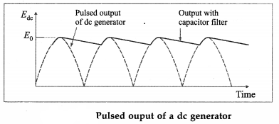
The output of a dc generator is a pulsating dc as shown in Fig. 12.22. For a smoother output, a capacitor filter is connected in parallel with the output (see below figure for reference).
![]()
Question 30
Explain back emf in a motor.
Answer:
A generator converts mechanical energy into electrical energy, whereas a motor converts electrical energy into mechanical energy. Also, motors and generators have the same construction. When the coil of a motor is rotated by the input emf, the changing magnetic flux through the coil induces an emf, consistent with Faraday’s law of induction. A motor thus acts as a generator whenever its coil rotates. According to Lenz’s law, this induced emf opposes any change, so that the input emf that powers the motor is opposed by the motor’s self-generated emf. This self-generated emf is called a back emf because it opposes the change producing it.
Question 31.
A motor draws more current when it starts than when it runs at its full (i.e., operating) speed. Explain.
OR
When a pump or refrigerator (or other large motor) starts up, lights in the same circuit dim briefly.
Answer:
The back emf is effectively the generator output of a motor, and is proportional to the angular velocity co of the motor. Hence, when the motor is first turned on, the back emf is zero and the coil receives the full input voltage. Thus, the motor draws maximum current when it is first turned on. As the motor speeds up, the back emf grows, always opposing the driving emf, and reduces the voltage across the coil and the amount of current it draws. This explains why a motor draws more current when it first comes on, than when it runs at its normal operating speed.
The effect is noticeable when a high power motor, like that of a pump, refrigerator or washing machine is first turned on. The large initial current causes the voltage at the outlets in the same circuit to drop. Due to the IR drop produced in feeder lines by the large current drawn by the motor, lights in the same circuit dim briefly.
[Note : A motor is designed to run at a certain speed for a given applied voltage. A mechanical overload on the motor slows it down appreciably. If the rotation speed is reduced, the back emf will not be as high as designed for and the current will increase. At too low speed, the large current can even burn its coil. On the other hand, if there is no mechanical load on the motor, its angular velocity will increase until the back emf is nearly equal to the driving emf. Then, the motor uses only enough energy to overcome friction.]
Question 32.
What is back torque in a generator?
Answer:
In an electric generator, the mechanical rotation of the armature induces an emf in its coil. This is the output emf of the generator. Under no-load condition, there is no current although the output emf exists, and it takes little effort to rotate the armature.
However, when a load current is drawn, the situation is similar to a current-carrying coil in an external magnetic field. Then, a torque is exerted, and this torque opposes the rotation. This is called back torque or counter torque.
Because of the back torque, the external agent has to apply a greater torque to keep the generator running. The greater the load current, the greater is the back torque.
33. Solve the following
Question 1.
An ac generator spinning at a rate of 750 rev/min produces a maximum emf of 45 V. At what angular speed does this generator produce a maximum emf of 102 V ?
Solution:
Data : e1 = 45 V, f1 = 750 rpm, e2 = 102 V
e = NABω = NAB(2πf) ∴ e ∝ f
∴\(\frac{e_{2}}{e_{1}}=\frac{f_{2}}{f_{1}}\)
∴ f2 = \(\frac{e_{2}}{e_{1}}\) × f1 = \(\frac{102}{45}\) × 750 = 1700 rpm
This is the required frequency of the generator coil.
Question 2.
An ac generator has a coil of 250 turns rotating at 60 Hz in a magnetic field of \(\frac{0.6}{\pi}\) T. What must be the area of each turn of the coil to produce a maximum emf of 180 V ?
Solution:
Data : N = 250, f = 60 Hz, B = \(\frac{0.6}{\pi}\) T
e0 = NABω = NAB (2πf)
∴ A = \(\frac{e_{0}}{N B 2 \pi f}=\frac{180}{(250)(0.6 / \pi)(2 \pi \times 60)}=\frac{18}{25 \times 72}\)
= 10-2 m2
This must be the area of each turn of the coil.
![]()
Question 3.
A dynamo attached to a bicycle has a 200 turn coil, each of area 0.10 m2. The coil rotates half a revolution per second and is placed in a uniform magnetic field of 0.02 T. Find the maximum voltage generated in the coil.
Solution:
Data : N = 200, A = 0.1 m2, f = 0.5 Hz, B = 0.02T
e0 = NABω = NAB (2πf)
Therefore, the maximum voltage generated,
e0 = (200)(0.1)(0.02)(2 × 3.142 × 0.5) = 1.26 V
Question 4.
A motor has a coil resistance of 5 Ω. If it draws 8.2 A when running at full speed and connected to a 220 V line, how large is the back emf ?
Solution:
Data : R = 5 Ω, I = 8.2 A, eappIied = 220 V
eappIied – eback =IR = 0
∴ eback = appIied – IR = 220 – (8.2)(5)
= 220 – 42 = 178 V
Question 5.
The back emf in a motor is 100 V when operating . at 2500 rpm. What would be the back emf at 1800 rpm? Assume the magnetic field remains unchanged.
Solution:
Data : e1 = 100 V, f1 = 2500 rpm, f2 = 1800 rpm
The back emf is proportional to the angular speed.
∴ \(\frac{e_{2}}{e_{1}}=\frac{f_{2}}{f_{1}}\)
∴ e2 = \(\frac{f_{2}}{f_{1}}\) × e1 = \(\frac{1800}{2500}\) × 100 = 72V
This is the back emf at lower speed.
Question 6.
The armature windings of a dc motor have a resistance of 10 Ω. The motor is connected to a 220 V line, and when the motor reaches full speed at normal load, the back emf is 160 V. Calculate
(a) the current when the motor is just starting up
(b) the current at full speed,
(c) What will be the current if the load causes it to run at half speed ?
Solution:
Data : R = 10 Ω, eappIied = 220 V, eback = 160 V,
f2 = f1/2 .
eappIied – eback – IR = 0
(a) At start up, back emf is zero.
∴ Istart = \(\frac{e_{\text {applied }}}{R}=\frac{220}{10}\) = 22 A
(b) At full speed,
Inormal = \(\frac{e_{\text {applied }}-e_{\text {back }}}{R}=\frac{220-160}{10}=\frac{60}{10}\) = 6 A
(c) Back emf is proprtional to rotational speed. Thus, if the motion is running at half the speed, back emf is half the original value, i.e., 80 V. Therefore, at half speed,
I2 = \(\frac{e_{\text {applied }}-e_{2}}{R}=\frac{220-80}{10}=\frac{140}{10}\) = 14 A
Question 34.
Find an expression for the power expended in pulling a conducting loop out of a magnetic field.
Answer:
When an external agent produces a relative motion between a conducting loop and an external magnetic field, a magnetic force resists the motion, requiring the applied force to do positive work. The work done is transferred to the material of the loop as thermal energy because of the electrical resistance of the material to the current that is induced by the motion.
Proof : Consider a rectangular wire loop ABCD of width l, with its plane perpendicular to a uniform magnetic field of induction \(\vec{B}\). The loop is being pulled out of the magnetic field at a constant speed v, as shown in below figure (a).
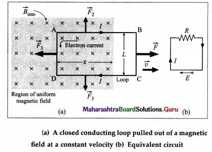
At any instant, let x be the length of the part of the loop in the magnetic field. As the loop moves to the right through a distance dx = vdt in time dt, the area of the loop inside the field changes by dA = ldx = lvdt. And, the change in the magnetic flux dΦm through the loop is
dΦm = BdA = Blvdt ………….. (1)
Then, the time rate of change of magnetic flux is
\(\frac{d \Phi_{\mathrm{m}}}{d t}=\frac{B l v d t}{d t}\) = B l v ……………. (2)
By Faraday’s second law, the magnitude of the induced emf is
|e| = \(\frac{d \Phi_{\mathrm{m}}}{d t}\) = B l v ………….. (3)
Due to the motion of the loop, the tree electrons (charge, e) in the wire inside the field experience Lorentz force \(e \vec{v} \times \vec{B}\). In the wire PQ this force moves the Free electrons 1mm P to Q making them travel in the anticlockwise sense around the 1oop. Therefore, the induced conventional current I is in the clockwise sense, as shown.
From figure (b) shows the equivalent circuit of the loop, where the induced emf e is a distributed emf and R is the total resistance of the loop.
∴ I = \(\frac{|e|}{R}=\frac{B l v}{R}\) …………… (4)
Now, a straight current carrying conductor of length L in a magnetic held experiences a torce
\(\vec{F}=I \vec{L} \times \vec{B}\)
whose direction can be found using Fleming’s Left hand rule.
Accordingly, forces \(\vec{F}_{2}\) and \(\vec{F}_{3}\) on wires AH and CD, respectively, are equal in magnitude (= Ix8), opposite in direction and have the same line of action- Hence, they balance each other. There is no torce on the wire BC as it hes outside the field.
The force \(\vec{F}_{1}\) on the wire AD has magnitude F1 = IlB and Is directed towards the left. To move the loop with constant velocity \(\vec{v}\), an external force \(\vec{F}=-\vec{F}_{1}\) must be applied. Therefore, in magnitude,
Because B, l and R are constants a force of constant magnitude F is required to move the loop at constant speed v.
Thus, the power or the rate of doing work by the external agent is
P = \(\vec{F} \cdot \vec{v}\) = Fv = \(\frac{B^{2} l^{2} v^{2}}{R}\) ………….. (5)
Question 35.
Why and where are eddy currents undesirable ? How are they minimized ?
Answer:
Eddy currents result in generation of heat (energy loss) in the cores of transformers, motors, induction coils, etc.
To minimize the eddy currents, instead of a solid metal block, cores are made of thin insulated metal strips or laminae.
![]()
Question 36.
If a magnet is dropped through a long thick- walled vertical copper tube, it attains a constant velocity after some time. Explain.
Answer:
Every thin transverse section of a thick-walled vertical copper tube is an annular disc. The downward motion of the magnet causes increased magnetic flux through such conducting discs. By Lenz’s . law, the induced or eddy current around the discs produces a magnetic field of its own to oppose the change in flux due to the magnet’s motion.
Initially, as the magnet falls under gravity, its speed increases. But, quickly the vertically upward force on the magnet due to the induced current becomes equal in magnitude to the gravitational force on the magnet and the net force on the magnet becomes zero. The subsequent motion of the magnet is at this constant terminal speed.
Question 37.
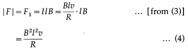
Describe in brief an experiment to demonstrate that eddy currents oppose the cause producing them.
Answer:
Apparatus : A strong electromagnet; two thick copper discs (4″ dia, \(\frac{1}{4}\)” thick), each attached to a rod about 30″ long. One of the discs has several vertical slots, about 80 % of the way up. The pendulums can be suspended from a lab stand by a pivot mount and made to oscillate between closely-spaced pole pieces of the electromagnet.
Experiment: When the electromagnet is not turned on, both the pendulums swing freely with some damping due to air resistance. When the electromagnet is turned on, the slotted pendulum still swings, although a little more damped, but the solid pendulum practically stops dead between the pole pieces of the magnet immediately.
Conclusion : As the pendulums enter or exit the magnetic field, the changing magnetic flux sets up eddy currents in the discs. The sense of the eddy currents is so as to produce a torque that opposes the rotation of the discs about their pivot. This opposing torque produces a breaking action, damping the oscillations.
In the case of the solid disc, the continuous volume of the disc offers large unbroken path to the swirling electrons. Thus, the eddy current builds up to a large magnitude. The thicker the disc, the larger is the eddy current and, consequently, the larger the damping.
In the case of the slotted disc, the vertical slots do not allow large eddy current and, consequently, the damping is small.
Question 38.
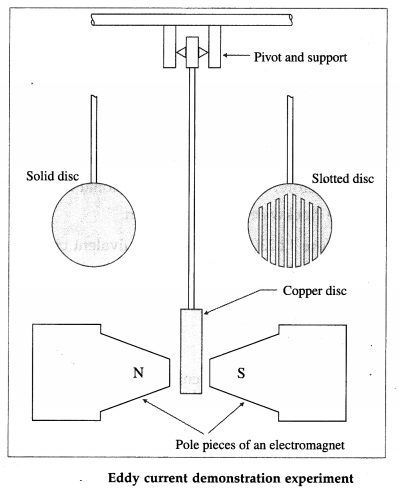
A solid conducting plate swings like a pendulum about a pivot into a region of uniform magnetic field, as shown in the diagram. As it enters and leaves the field, show and explain the directions of the eddy current induced in the plate and the force on the plate.
Answer:
Figure shows the eddy currents in the conducting plate as it enters and leaves the magnetic field. In both cases, it experiences a force \(\vec{F}\) opposing its motion. As the plate enters from the left, the magnetic flux through the plate increases. This sets up an eddy current in the anticlockwise direction, as shown. Since only the right-hand side of the current loop is inside the field, by Fleming’s right hand rule (FRH rule), an unopposed force acts on it to the left. There is no eddy current once the plate is completely inside the uniform field. When the plate leaves the field on the right, the decreasing flux causes an eddy current in the clockwise direction. The damping magnetic force on the current is to the left, further slowing the motion.
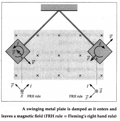
The eddy current in the plate results in mechanical energy being dissipated as thermal energy. Each time the plate enters and leaves the field, a part of its mechanical energy is transformed into thermal energy. After a few swings, the mechanical energy becomes zero and the motion comes to a stop with the warmed-up plate hanging vertically.
39. Solve the following
Question 1.
A metal rod of resistance of 15 Ω is moved to the right at a constant 60 cm/s along two parallel conducting rails-25 cm apart and shorted at one end. A magnetic field of magnitude 0.35 T points into the page, (a) What are the induced emf and current in the rod? (b) At what rate is thermal energy generated?
Solution:
Data: R = 15Ω, v = 0.6 m/s, l = 0.25m, B = 0.35T
(a) Induced emf, e = Blv = (0.35)(0.25)(0.6)
= 0.0525 V = 52.5 mV
The current in the rod, I = \(\frac{e}{\mathrm{R}}=\frac{52.5}{15}\) = 3 5 mA
(b) Power dissipated, P = eI = 0.0525 × 3.5 × 10-4
= 0.184 mW
![]()
Question 2.
A conducting rod 10 cm long is being pulled along horizontal, frictionless conducting rails at a con-stant 5 m/s. The rails are shorted at one end with a metal strip. There is a uniform magnetic field of strength 1.2 T out of the page in the region in which the rod moves. If the resistance of the rod is 0.5 Ω, what is the power of the external agent pulling the rod? Assume that the resistance of the rails is negligibly small.
Solution:
Data: l = 0.1 m, B = 1.2T, v = 5 m/s. R = 0.5 Ω
Power, P = \(\frac{(B l v)^{2}}{R}=\frac{(1.2 \times 0.1 \times 5)^{2}}{0.5}\) = 0.72 W
Question 40.
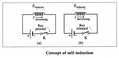
Explain the concept of self induction.
Answer:
Consider an isolated coil or circuit in which there is a current I. The current produces a magnetic flux linked with the coil.
The magnetic flux linked with the coil can be changed by varying the current in the coil itself, e.g., by breaking and closing the circuit. This produces a self-induced emf in the coil, called a back emf because it opposes the change producing it. It sets up an induced current in the coil itself in the same direction as the original current opposing its decrease when the key K is suddenly opened. When the key K is closed, the induced current is opposite to the conventional current, opposing its increase.
When the current through a coil changes continuously, e.g., by a time-varying applied emf, the magnetic flux linked with the coil also goes on changing.
The production of induced emf in a coil, due to the changes of current in the same coil, is called self induction.
Question 41.
Explain and define the self inductance of a coil.
OR
Define the coefficient of self induction.
Answer:
When the current through a coil goes on changing, the magnetic flux linked with the coil also goes on changing. The magnetic flux (NΦm) linked with the coil at any instant is directly proportional to the current (I) through the coil at that instant.
NΦm ∝ I
∴ NΦm = LI
where L is a constant, dependent on the geometry of the coil, called the self inductance or the coefficient, of self induction of the coil.
The self-induced emf in the coil is
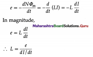
Definition : The self inductance or the coefficient of self induction of a coil is defined as the emf induced in the coil per unit time rate of change of current in the same coil. OR (using L = NΦm/I), the self inductance of a coil is the ratio of magnetic flux linked with the coil to the current in it.
Question 42.
State and define the SI unit of self inductance. Give its dimensions.
OR
Write the SI unit and dimensions of the coefficient of self induction.
Answer:
The SI unit of self inductance or coefficient of self induction or inductance as it is commonly called is called the henry (H).
The self-inductance of a coil is 1 henry, if an emf of 1 volt is induced in the coil when the current through the same coil changes at the rate of 1 ampere per second.
The dimensions of self inductance or coefficient of self induction are [ML2T-2I-2].
1 henry = 1 H = 1 V/A.s = 1 T.m2/A
[ Note : The unit henry is named in honour of Joseph Henry (1797-1878) US physicist.]
Question 43.
What is an inductor?
Answer:
An inductor is a coil of wire with significant self inductance. If the coil is wound on a nonmagnetic cylinder or former, such as ceramic or plastic, it is called an air-core inductor; its circuit symbol is ![]() . If the cod is wound on a magnetic former. such as laminated iron or ferrite. it Is called an iron core inductor; its circuit symbol is
. If the cod is wound on a magnetic former. such as laminated iron or ferrite. it Is called an iron core inductor; its circuit symbol is ![]() .
.
![]()
Question 44.
Current passes through a coil shown from left to right. In which direction is th induced emf. if the current is (a) increasing with time (b) decreasing in time?
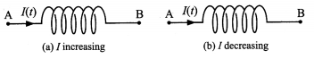
Answer:
From Lent’s law, the induced emf must oppose the diange in the magnetic flux. (a) When the current mcreases to the right, so is the magnetic flux. To oppose the increasing flux to the tight. the induced emi Is to the left. i.e.. the point A is at a positive potential relative to point B.
(b) When the current to the right is decreasing the induced emf acts to boost up the flux to the right and points to the tight, so that the point A is at a negative potential relative to point B.
Question 45.
Derive an expression for the energy stored in the magnetic field of an inductor.
OR
Derive an expression for the electrical work done in establishing a steady current in a coil of self inductance L.
Answer:
Consider an inductor of sell inductance L connected in a circuit When the circuit is dosed, the current in the circuit increases and so does the magnetic flux linked with the coiL At any instant the magnitude of the induced emf is
e = L \(\frac{d i}{d t}\)
The power consumed in the inductor is
P = ei = L \(\frac{d i}{d t}\) ∙ i
[Alternatively, the work done in moving a charge dq against this emf e is
dw = edq = L \(\frac{d i}{d t}\) ∙ dq = Li ∙ di (∵ \(\frac{d q}{d t}\) = i)
This work done is stored in the magnetic field of the inductor. dw = du.]
The total energy stored In the magnetic field when the current increases from 0 to I In a time interval from 0 to t can be determined by integrating this expression :
Um = \(\int_{0}^{t} P d t=\int_{0}^{I} L i d i=L \int_{0}^{I} i d i=\frac{1}{2} L I^{2}\)
which is the required expression for the stored magnetic energy.
[Note: Compare this with the electric energy stored in a capacitor, Ue = \(\frac{1}{2}\)CV2]
Question 46.
State the expression for the energy stored in’the magnetic field of an inductor. Hence, define its self inductance.
Answer:
When a steady current is passed through an inductor of self inductance L the energy stored in the
magnetic field of the inductor is Um = \(\frac{1}{2}\)Li2]. Therefore, for unit current, L = 2Um
Hence, we may define the self inductance of a coil as numerically equal to twice the energy stored in its magnetic field for unit current through the inductor.
Question 47.
What is the role of an inductor in an ac circuit ?
Answer:
As a circuit element, an inductor slows down changes in the current in the circuit. Thus, it provides an electrical inertia and is said to act as a ballast. In a non-inductive coil (L ≅ 0), electrical energy is converted into heat due to ohmic resistance of the coil (Joule heating). On the other hand, an inductive coil or an inductor stores part of the energy in the magnetic field of its coils when the current through it is increasing; this energy is released when the current is decreasing. Thus, an inductor limits an alternating current more efficiently than a non-inductive coil or a pure resistor.
Question 48.
State the expressions for the effective or equivalent inductance of a combination of a number of inductors connected (a) in series (b) in parallel. Assume that their mutual inductance can be ignored.
Answer:
We assume that the inductors are so far apart that their mutual inductance is negligible.
(a) For a series combination of a number of inductors, L1, L2, L3, …, the equivalent inductance is
Lseries = L1 + L2 + L3+ ……..
(b) For a parallel combination of a number of inductors, L1, L2, L3, …, the equivalent inductance is
\(\frac{1}{L_{\text {parallel }}}=\frac{1}{L_{1}}+\frac{1}{L_{2}}+\frac{1}{L_{3}}+\ldots\)
![]()
Question 49.
Obtain an expression for the self inductance of a solenoid.
Answer:
Consider a long air-cored solenoid of length Z, diameter d and N turns of wire. We assume that the length of the solenoid is much greater than its diameter so that the magnetic field inside the solenoid may considered to be uniform, that is, end effects in the solenoid can be ignored. With a steady current I in the solenoid, the magnetic field within the solenoid is
B = µ0nI ………….. (1)
where n = N/l is the number of turns per unit length. So the magnetic flux through one turn is
Φm = BA = µ0nIA ……….. (2)
Hence, the self inductance of the solenoid,
L = \(\frac{N \Phi_{\mathrm{m}}}{I}\) =(nl)µ0nA = µ0n2lA = µ0n2 V ………….. (3)
= µ0n2l\(\frac{\pi d^{2}}{4}\) …………. (4)
where V = lA is the interior volume of the solenoid. Equation (3) or (4) gives the required expression.
[Note: It is evident thatthe self inductance of a long solenoid depends only on its physical properties – such as the number of turns of wire per unit length and the volume, and not on the magnetic field or the current. This is true for inductors in general.] .
Question 50.
State the expression for the self inductance of a solenoid. Hence show that the SI unit of magnetic permeability is the henry per metre.
Answer:
The self inductance of an air-cored long solenoid of volume V and number of turns per unit length n is L = µ0n2V. Since [n2] = [L-2], n2V has the dimension of length. The SI unit of the L being the henry, the SI unit of magnetic permeability (µ0) is the henry per metre (H / m). .
µ0 = 4π × 10-7 H/m = 4π × 10-7 T∙m/A
Question 51.
Derive an expression for the self inductance of a narrow air-cored toroid of circular cross section.
Answer:
Consider a narrow air-cored toroid of circular cross section of radius r, central radius R and number of turns N. So that, assuming r << R, the magnetic field in the toroidal cavity is considered to be uniform, equal to
B = \(\frac{\mu_{0} N I}{2 \pi R}\) = µ0nI ………….. (1)
where n = \(\frac{N}{2 \pi R}\) is the number of turns of the wire 2nR per unit length. The area of cross section, A = πr2.
The magnetic flux through one turn is
Φm = BA = µ0nIA ………… (2)
Hence, the self inductance of the toroid,
L = \(\frac{N \Phi_{\mathrm{m}}}{I}\) = (2πRn) µ0nA = µ02πRn2A = µ0n2V …………… (3)
= \(\frac{\mu_{0} N^{2} r^{2}}{2 R}\) ………….. (4)
where V = 2πRA is the volume of the toroidal cavity. Equation (3) or (4) gives the required expression.
Question 52.
Obtain an expression for the energy density of a magnetic field.
Answer:
Consider a short length ¡ near the middle of a long, tightly wound solenoid, of cross-sectional area A, number of turns per unit length n and carrying a steady current I. For such a solenoid, the magnetic field is approximately uniform everywhere inside and zero outside. So, the magnetic energy Um stored by this length l of the solenoid lies entirely within the volume Al.
The magnetic field inside the solenoid is
B = µ0nI …………… (1)
and if L be the inductance of length l of the solenoid,
L = µ0 n2lA …………… (2)
The stored magnetic energy,
Um = \(\frac{1}{2}\)LI2 …………. (3)
and the energy density of the magnetic field (energy per unit volume) is
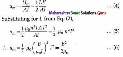
Equation (6) gives the magnetic energy density in vacuum at any point in a magnetic field of induction B, irrespective of how the field is produced.
[Note : Compare Eq.(6) with the electric energy density in vacuum at any point in an electric field of intensity
e, ue = \(\frac{1}{2}\) ε0e2. Both ue and um are proportional to the square of the appropriate field magnitude.]
![]()
Question 53.
Determine the magnetic energy stored per unit length of a coaxial cable, represented by two coaxial cylindrical shells of radii a (inner) and b (outer), and carrying a current I. Hence derive an expression for the self inductance of the coaxial cable of length l.
Answer:
Figure (a) shows a coaxial cable represented by two hollow, concentric cylindrical conductors along which there is electric current in opposite directions. The magnetic field between the conductors can be found by applying Ampere’s law to the dashed path of radius r{a < r < b) in figure (a). Because of the cylindrical symmetry, B is constant along the path, and
\(\oint \vec{B} \cdot \overrightarrow{d l}\) = B (2πr) = u0I
∴ B = \(\frac{\mu_{0} I}{2 \pi r}\) ……………… (1)
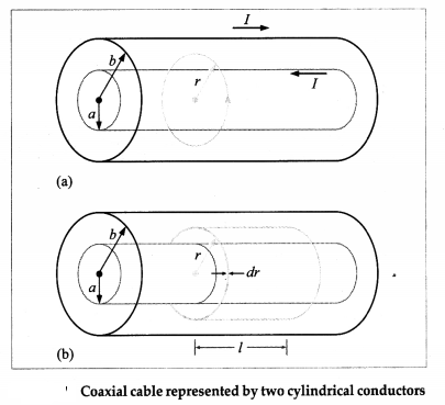
A similar application of Ampere’s law for r > b and r < a, shows that B = 0 in both the regions. Therefore, all the magnetic energy is stored between the two conductors of the cable.
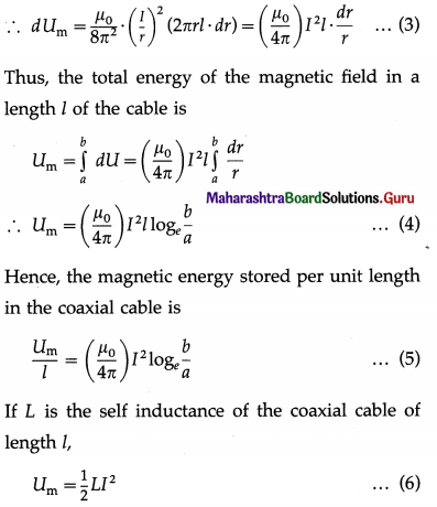
The energy density of the magnetic field is
um = \(\frac{B^{2}}{2 \mu_{0}}\) …………….. (2)
Therefore, substituting for B from Eq. (1) into Eq. (2), the magnetic energy stored in a cylindrical shell of radius r, thickness dr and length l is
dUm = umdV = um(2πr ∙ dr ∙ l)
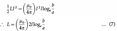
Equating the right hand sides of Eqs. (4) and (6),
54. Solve the following
Question 1.
A coil of self inductance 5 H is connected in series with a switch and a battery. After the switch is closed, the steady state value of the current is 5 A. The switch is then suddenly opened, causing the current to drop to zero in 0.2 s. Find the emf developed across the inductor (coil) as the switch is opened.
Solution:
Data : L = 5 H, Ii = 5 A, If = 0, ∆t = 0.2 s
The rate of change of current,
\(\frac{d I}{d t}=\frac{I_{\mathrm{f}}-I_{\mathrm{i}}}{\Delta t}=\frac{0-5}{0.2}\) = – 25 A/s
∴ The induced emf,
e = -L \(\frac{d I}{d t}\) = -5(-25) = 125 V
Question 2.
A toroidal coil has an inductance of 47 mH. Find the maximum self-induced emf in the coil when the current in it is reversed from 15 A to -15 A in 0.01 s.
Solution:
Data : L = 4.7 × 10⁻² H, Ii = 15A, Ii = -15 A,
∆f = 0.01 s
The rate of change of current,
\(\frac{d I}{d t}=\frac{I_{\mathrm{f}}-I_{\mathrm{i}}}{\Delta t}=\frac{(-15)-15}{0.01}\) = – 3000 A/s
∴ The maximum self-induced emf,
e = – L \(\frac{d I}{d t}\) (4.7 × 10⁻²) (- 3000) = 141 V
![]()
Question 3.
An emf of 2 V is induced in a closely-wound coil of 50 turns when the current through it increases uniformly from O to 5 A in 0.1 s. (a) What is the self inductance of the coil? (b) What is the flux through each turn of the coil for a steady current at 5A?
Solution:
Data : e = 2 V, N = 50, Ii = 0, If = 5A, ∆t = 0.1 s
(a) The rate of change of current
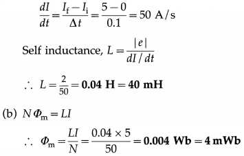
This is the flux through each turn.
Question 4.
At the instant the current through a coil is 0.2 A, the energy stored in its magnetic field is 6 mJ. What is the self indudance of the coil ?
Solution:
Data: I = 0.2A, Um = 6 × 10⁻³ J
Um = \(\frac{1}{2}\) LI2
Therefore, self inductance of the coil is
Question 5.
A coil of self inductance 3 H and resistance 100 Ω carries a steady current of 2 A. (a) What is the energy stored in the magnetic field of the coil? (b) What is the energy per second dissipated in the resistance of the coil ?
Solution:
Data : L = 3 H, R = 100 Ω, I = 2 A
(a) Magnetic energy stored,
Um = \(\frac{1}{2}\) LI2 = \(\frac{1}{2}\) (3) (2)2 = 6 J
(b) Power dissipated in the resistance of the coil,
P = I2R = (2)2(100) = 400 W
Question 6.
A 10 H inductor carries a current of 25 A. Flow much ice at 0 °C could be melted by the energy stored in the magnetic field of the inductor ? [Latent heat of fusion of ice, Lf = 335 J/g]
Solution:
Data : L = 10 H, Z = 25 A, Lf = 335 J/g
Magnetic energy stored,
Um = \(\frac{1}{2}\) LI2 = \(\frac{1}{2}\) (10) (25)2 = 3125 J
Heat energy required to melt ice at 0 °C of mass m,
H = mLf
Equating H with Um,
m = \(\frac{U_{\mathrm{m}}}{L_{\mathrm{f}}}=\frac{3125}{335}\) = 9.328 g
Therefore, 9.328 g of ice could be melted by the energy stored.
![]()
Question 7.
A solenoid 40 cm long has a cross-sectional area of 0.9 cm2 and is tightly wound with wire of diameter 1 mm. Calculate the self inductance of the solenoid.
Solution:
Data : D = 1 mm, l = 40 cm = 0.4 m, A = 0.9 cm2 = 9 × 10⁻⁵ m2, Ii = 10 A, If = 0, ∆t = 0.1 s,
μ0 = 4π × 10-7 H/m
The number of turns per unit length,
n = \(\frac{1}{1 \mathrm{~mm}}\) = 1 mm-1 = 103 m-1
Self inductance of the solenoid,
L = μ0n2lA = (4π × 10-7)(103)2(0.4)(9 × 10⁻⁵)
= 16 × 9 × 3.142 × 10-7 = 4.524 × 10⁻⁵ H
Question 8.
A solenoid of 1000 turns is wound with wire of diameter 0.1 cm and has a self inductance of 2.4 π × 10-5 H. Find (a) the cross-sectional area of the solenoid (b) the magnetic flux through one turn of the solenoid when a current of 3 A flows through it.
Solution:
Data: N = 1000, D = 0.1 cm, L = 2.4π × 10-5 H,
I = 3A, μ0 = 4π × 10-7 H/m
The number of turns per unit length.
n = \(\frac{1}{1 \mathrm{~mm}}\) = 1 mm-1 = 103 m-1
and the length of the solenoid,
l = ND = 1000 × 0.1 = 100 cm = 1 m
L = μ0n2lA
(a) The area of cross section,
A = \(\frac{L}{\mu_{0} n^{2} l}=\frac{2.4 \pi \times 10^{-5}}{\left(4 \pi \times 10^{-7}\right)\left(10^{3}\right)^{2}(1)}=\frac{24 \pi}{4 \pi} \times 10^{-5}\)
= 6 × 10⁻⁵ m2
(b) Magnetic flux through one turn,
Φm = BA = (μ0nI)A
= (4π × 10-7)(103)(3)(6 × 10⁻⁵)
= 72π × 10-9 Wb
Question 9.
A toroid of circular cross section of radius 0.05 m has 2000 windings and a self inductance of 0.04 H. What is (a) the current through the windings when the energy in its magnetic field is 2 × 10⁻⁶ J (b) the central radius of the toroid ?
Solution:
Data : r = 0.05 m, N = 2000, L = 0.04 H,
Um = 2 × 10⁻⁶ J, μ0 = 4π × 10-7 H/m
(a) Um = \(\frac{1}{2}\) LI2
Therefore, the current in the windings,
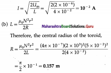
Question 10.
A coaxial cable, whose outer radius is five times its inner radius, is carrying a current of 1.5 A. What is the magnetic field energy stored in a 2 m length of the cable ?
Solution:
Data : b/a = 5, I = 1.5A, l = 2m, \(\frac{\mu_{0}}{4 \pi}\) = 10-7 H/m
The total magnetic energy in a given length of a current-carrying coaxial cable,
Um = \(\left(\frac{\mu_{0}}{4 \pi}\right) I^{2} l \log _{e} \frac{b}{a}\)
Therefore, the required magnetic energy is
Um = (10-7)(1.5)2(2)loge5
= 4.5 × 107 × 2.303 × log105
= 4.5 × 10-7 × 2.303 × 0.6990 = 7.24 × 10⁻⁷ J
Question 55.
Explain the concept/phenomenon of mutual induction.
OR
Explain and define mutual inductance of a coil with respect to another coil.
OR
Define the coefficient of mutual induction.
Answer:
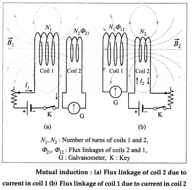
The production of induced emf in a coil due to the change of current in the same coil is called self induction.
In above figure (a), a current I1 in coil 1 sets up a magnetic flux Φ21 through one turn of a neighbouring coil 2, magnetically linking the two coils. Then, the flux through the N2 turns of coil 2, i.e., the flux linkage of coil 2, is N2Φ21.
N2Φ21 ∝ I1
∴ N2Φ21 = M21I1 …………. (1)
where the constant of proportionality, M21, is called the coefficient of mutual induction of coil 2 with respect to coil 1. If the current I1 in coil 1 changes with time, the varying flux linkage induces an emf e2 in coil 2.
e2 = – \(\frac{d}{d t}\) (N2Φ21) = – M21 \(\frac{d I_{1}}{d t}\) …………. (2)
Similarly, if we interchange the roles of the two coils and set up a current I2 in coil 2 [from figure (b)], Then, the flux linkage of N1 turns of coil 1 is N1Φ12 and
N1Φ12 = M12I2 ………… (3)
where M12 is the coefficient of mutual induction of coil 1 with respect to coil 2. And, for a varying current I2(t), the induced emf in coil 1 is
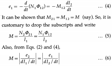
We define mutual inductance using Eq. (5) or Eq. (6).
The mutual inductance or the coefficient of mutual induction of two magnetically linked coils is equal to the flux linkage of one coil per unit current in the neighbouring coil.
OR
The mutual inductance or the coefficient of mutual induction of two magnetically linked coils is numerically equal to the emf induced in one coil (secondary) per unit time rate of change of current in the neighbouring coil (primary).
Question 56.
State and define the SI unit of mutual inductance. Give its dimensions.
Answer:
The SI unit of mutual inductance is called the henry (H).
The mutual inductance of a coil (secondary) with respect to a magnetically linked neighbouring coil (primary) is one henry if an emf of 1 volt is induced in the secondary coil when the current in the primary coil changes at the rate of 1 ampere per second.
The dimensions of mutual inductance are [ML2T-2I-2] (the same as those of self inductance).
![]()
Question 57.
Two coils A and B have mutual inductance 2 × 10⁻² H. If the current in the coil A is 5 sin (10πt) ampere, find the maximum emf induced in the coil B.
Ans;
The emf induced in the coil B,
|eB| = M \(\frac{d I_{\mathrm{A}}}{d t}\)
=(2 × 10⁻²)[5 cos (10πt)] × 10π
∴ |eB|max = π volts.
Question 58.
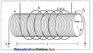
A long solenoid, of radius R, has n turns per unit length. An insulated coil C of IV turns is wound over it as shown. Show that the mutual inductance for the coil-solenoid combination is given by M = μ0πR2nN.
Answer:
We assume the solenoid to be ideal and that all the flux from the solenoid passes through the outer coil C. For a steady current Is through the solenoid, the uniform magnetic field inside the solenoid is
B = μ0nIs ……………… (1)
Then, the magnetic flux through each turn of the coil due to the current in the solenoid is
ΦCS = BA = (μ0nIs)(πR2) ………….. (2)
Thus, their mutual inductance is
M = \(\frac{N \Phi_{\mathrm{CS}}}{I_{\mathrm{S}}}\) = μ0πR2nN ………….. (3)
Equation (2) is true as long as the magnetic field of the solenoid is entirely contained within the cross section of the coil C. Hence, M does not depend on the shape, size, or possible lack of close packing of the coil.
Question 59.
A solenoid of N1 turns has length l1 and radius R1, and a second smaller solenoid of N2 turns has length l2 and radius R2. The smaller solenoid is placed coaxially and completely inside the larger solenoid. What is their mutual inductance ?
Answer:
Assuming the larger solenoid to be ideal, the magnetic field within it may be considered uniform, so the flux through the small solenoid due to the larger solenoid is also uniform. Assuming a current I1 in the larger solenoid, the magnitude of the magnetic field at points within the small solenoid due to the larger one is
B1 = μ0\(\frac{N_{1}}{l_{1}}\) I1
Then, the flux Φ21 through each turn of the small coil is
Φ21 = B1A2
where is A2 = πR22, the area enclosed by the turn. Thus, the flux linkage in the small solenoid with its N2 turns is
N2Φ21 = N2B1A2
Thus, their mutual inductance is
M = \(\frac{N_{2} \Phi_{21}}{I_{1}}=N_{2}\left(\mu_{0} \frac{N_{1}}{l_{1}}\right)\left(\pi R_{2}^{2}\right)=\mu_{0} \pi \frac{N_{1} N_{2}}{l_{1}} R_{2}^{2}\)
which is the required expression.
Question 60.
What is meant by coefficient of magnetic coupling?
Answer:
For two inductively coupled coils, the fraction of the magnetic flux produced by the current in one coil (primary) that is linked with the other coil (secondary) is called the coefficient of magnetic coupling between the two coils.
The coupling coefficient K shows how good the coupling between the two coils is; 0 ≤ K ≤ 1. In the ideal case when all the flux of the primary passes through the secondary, K=l. For coils which are not coupled, K = 0. Two coils are tightly coupled if K > 0.5 and loosely coupled if K < 0.5.
[ Note ; For iron-core coupled circuits, the value of K may be as high as 0.99, for air-core coupled circuits, K varies between 0.4 to 0.8. ]
![]()
Question 61.
State the factors which magnetic coupling coefficient of two coils depends on.
Answer:
The coefficient of magnetic coupling between two coils depends on
- the permeability of the core on which the coils are wound
- the distance between the coils
- the angle between the coil axes.
Question 62.
When is the magnetic coupling coefficient of two coils (i) maximum (ii) minimum?
Answer:
The coefficient of magnetic coupling between two coils is
- maximum when the coils are wound on the same ferrite (iron) core such that the flux linkage is maximum,
- minimum for air-cored coils with the coil axes perpendicular.
Question 63.
Show that the mutual inductance for a pair of inductively coupled coils/circuits of self inductances L1 and L2 is given by M = K\(\sqrt{L_{1} L_{2}}\), where K is the coupling coefficient.
Answer:
Consider a pair of inductively coupled coils having N1 and N2 turns, shown in figure
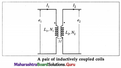
A current l1(t) sets up a flux N1Φ1(t) in coil 1 and induces a current l2(t) and flux N2Φ2(t) in coil 2. Then, the self inductances of the coils are
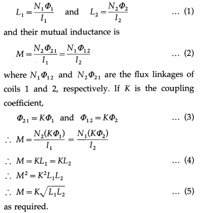
Alternate method :
Consider a pair of inductively coupled coils shown in above figure.We assume that I1(t), I2(t) are zero at t = 0. as also the magnetic energy of the system.
The induced emfs are
![]()
The net energy Input to the system shown in figure at time t is given by
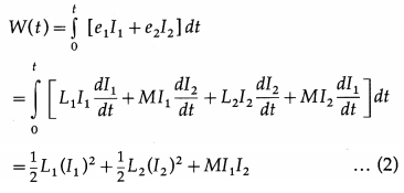
If one current enters a dot marked terminal while the other leaves a dot marked terminal, Eq. (2) becomes
W(t) = \(\frac{1}{2}\) L1(I1)2 + \(\frac{1}{2}\) L2(I1)2 – MI1I2 …………. (3)
The net electrical energy input to the system is non-negative, W(t) ≥ 0. We rearrange Eq.(3) as
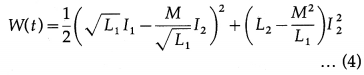
The first term in the parenthesis on the right hand side of Eq. (4) is positive for all values of I1 and I2 Thus, for the second term also to be non-negative,
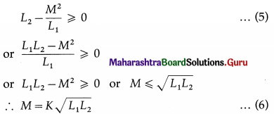
where the coupling coefficient K is a non-negtive number, 0 ≤ K ≤ 1, and is independent of the reference directions of the currents in the coils.
Question 64.
What is a transformer?
State the principle of working of a transformer.
Answer:
A transformer is an electrical device which uses mutual induction to transform electrical power at one alternating voltage into electrical power at another alternating voltage (usually different), without change of frequency of the voltage.
Principle : A transformer works on the principle that a changing current through one coil creates a changing magnetic flux through an adjacent coil which in turn induces an emf and a current in the second coil.
Question 65.
What are step-up and step-down transformers?
Answer:
- Step-up transformer : It increases the amplitude of the alternating emf, i.e., it changes a low voltage alternating emf into a high voltage alternating emf with a lower current.
- Step-down transformer : It decreases the amplitude of the alternating emf, i.e., it changes a high voltage alternating emf into a low voltage alternating emf with a higher current.
![]()
Question 66.
Describe the construction and working of a transformer with a neat labelled diagram.
Answer:
Construction : A transformer consists of two coils, primary and secondary, wound on two arms of a rectangular frame called the core.
(1) Primary coil : It consists of an insulated copper wire wound on one arm of the core. Input voltage is applied at the ends of this coil.
In a step-up transformer, thick copper wire is used for primary coil. In a step-down transformer, thin copper wire is used for primary coil.
(2) Secondary coil : It consists of an insulated copper wire wound on the other arm of the core. The output voltage is obtained at the ends of this coil.
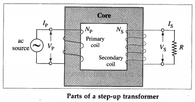
In a step-up transformer, thin copper wire is used for secondary coil. In a step-down transformer, thick copper wire is used for secondary coil.
(3) Core : It consists of thin rectangular frames of soft iron stacked together, but insulated from each other. A core prepared by stacking thin sheets rather than using a single thick sheet helps reduce eddy currents.
Working : When the terminals of the primary coil are connected to a source of an alternating emf (input voltage), there is an alternating current through it. The alternating current produces a time varying magnetic field in the core of the transformer. The magnetic flux associated with the secondary coil thus varies periodically with time according to the current in the primary coil. Therefore, an alternating emf (output voltage) is induced in the secondary coil.
Question 67.
Derive the relationship \(\frac{V_{\mathrm{P}}}{V_{\mathrm{S}}}=\frac{I_{\mathrm{S}}}{I_{\mathrm{P}}}\) for a transformer.
Answer:
An alternating emf VP from an ac source is applied across the primary coil of a transformer. This sets up an alternating current IP in the primary circuit and also produces an alternating magnetic flux through the primary coil such that
VP = -NP \(\frac{d \Phi_{\mathrm{P}}}{d t}\),
where NP is the number of turns of the primary coil and ΦP is the magnetic flux through each turn.
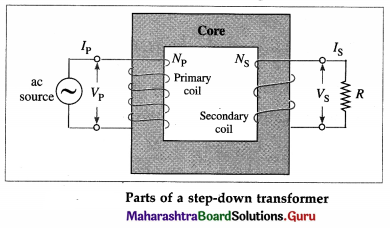
Assuming an ideal transformer (i.e., there is no leakage of magnetic flux), the same magnetic flux links both the primary and the secondary coils,
i. e., ΦP = ΦS
As a result, the alternating emf induced in the secondary coil,
VS = = NS \(\frac{d \Phi_{\mathrm{S}}}{d t}\) = – NS \(\frac{d \Phi_{\mathrm{P}}}{d t}\)
where NS is the number of turns of the secondary coil. If the secondary circuit is completed by a resistance R, the secondary current is IS = VS/R, assuming the resistance of the coil to be far less than R. Ignoring power losses, the power delivered to the primary coil equals that taken out of the secondary coil, so VPIP = VSIS.
∴ \(\frac{V_{\mathrm{P}}}{V_{\mathrm{S}}}=\frac{I_{\mathrm{S}}}{I_{\mathrm{P}}}\)
which is the required expression.
![]()
Question 68.
Derive the relation \(\frac{V_{\mathrm{S}}}{V_{\mathrm{P}}}=\frac{N_{\mathrm{S}}}{N_{\mathrm{P}}}\) for a transformer. Hence, explain a step-up and a step-down trans-former. Also, show that \(\frac{I_{P}}{I_{\mathrm{S}}}=\frac{N_{\mathrm{S}}}{N_{\mathrm{P}}}\)
OR
Derive expressions for the emf and current for a transformer in terms of the turns ratio.
Answer:
An alternating emf VP from an ac source is applied across the primary coil of a transformer, shown in figure.
This sets up an alternating current fP in the primary circuit and also produces an alternating magnetic flux through the primary coil such that
VP = -NP \(\frac{d \Phi_{\mathrm{P}}}{d t}\) ………….. (1)
where NP is the number of turns of the primary coil and ΦP is the magnetic flux through each turn.
Assuming an ideal transformer (i.e., there is no leakage of magnetic flux), the same magnetic flux links both the primary and the secondary coils, i.e., ΦP = ΦS.
As a result, the alternating emf induced in the secondary coil,
VS = – NS \(\frac{d \Phi_{\mathrm{S}}}{d t}\) = – NS \(\frac{d \Phi_{\mathrm{P}}}{d t}\) ……………… (2)
where NS is the number of turns of the secondary coil.
From Eqs. (1) and (2),
\(\frac{V_{\mathrm{S}}}{V_{\mathrm{P}}}=\frac{N_{\mathrm{S}}}{N_{\mathrm{P}}}\) or VS = VP \(\frac{N_{\mathrm{S}}}{N_{\mathrm{P}}}\) …………… (3)
Case (1) i If NS > NP, VS > VP. Then, the trans-former is called a step-up transformer.
Case (2) : If NS < NP, VS < VP. Then the transformer is called a step-down transformer.
Ignoring power losses, the power delivered to the primary coil equals that taken out of the secondary coil, so that VPIP = VSIS …………. (4)
From Eqs. (3) and (4),
\(\frac{I_{\mathrm{P}}}{I_{\mathrm{S}}}=\frac{V_{\mathrm{S}}}{V_{\mathrm{P}}}=\frac{N_{\mathrm{S}}}{N_{\mathrm{P}}}\)
Question 69.
What is the turns ratio of a transformer? What can you say about its value for a (1) step-up transformer (2) step-down transformer?
Answer:
The ratio of the number of turns in the secondary coil (NS) to that in the primary coil (NP) is called the turns ratio of a transformer.
The turns ratio \(\frac{N_{\mathrm{S}}}{N_{\mathrm{P}}}\) > 1 for a step-up transformer.
The turns ratio \(\frac{N_{\mathrm{S}}}{N_{\mathrm{P}}}\) < 1 for a step-down transformer.
Question 70.
State any two factors on which the maximum value of the alternating emf induced in the secondary coil of a transformer depends.
Answer:
The maximum value of the alternating emf induced in the secondary coil of a transformer depends on
- the ratio of the number of turns of the secondary coil to that of the primary coil
- the maximum value of the alternating emf applied to the primary coil
- the core of the transformer.
Question 71.
The primary coil of a transformer has 100 turns and the secondary coil has 200 turns. If the peak value of the alternating emf applied to the primary coil is 100 V, what is the peak value of the alternating emf obtained across the secondary coil?
Answer:
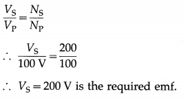
![]()
Question 72.
Distinguish between a step-up and a step-down transformers. (Any two points)
Answer:
| Step-up transformer | Step-down transformer |
| 1. The output voltage is more than the input voltage. | 1. The output voltage is less than the input voltage. |
| 2. The number of turns of the secondary coil is more than that of the primary coil. | 2. The number of turns of the secondary coil is less than that of the primary coil. |
| 3. The output current is less than the input current. | 3. The output current is more than that of the input current. |
| 4. The primary coil is made of thicker copper wire than the secondary coil. | 4. The secondary coil is made of thicker copper wire than the primary coil. |
72. Solve the following
Question 1.
When a current changes from 4 A to 12 A in 0.5 s in the primary coil, an induced emf of 50 mV is generated in the secondary coil. What is the mutual inductance between the two coils ? What will be the emf induced in the secondary, if the current in the primary changes from 3 A to 9 A in 0.02 s ?
Solution:
Data : Ii1 =4 A, If1 = 12 A, ∆t1 = 0.5 s, ∆t2 = 0.02 s
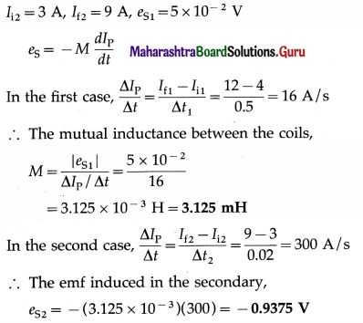
Question 2.
A plane coil of lo turns is tightly wound around a solenoid of diameter 2 cm having 400 turns per centimeter. The relative permeability of the core is 800. Calculate the mutual inductance.
Solution:
Data: N = 10, R = 1 cm = 10-2 m,
n = 400 cm-1 = 4 × 10⁴ m-1, k = 800,
μ0 = 4π × 104 H/m
Mutual inductance,
M = kμ0πR2nN
=(800)(4π × 10-7)[π × (102)2](4 × 104)(10)
= 0.1264 H
Question 3.
Two coils of 100 turns and 200 turns have self inductances 25 mH and 40 mH, respectively. Their mutual inductance is 3 mH. If a 6 mA current in the first coil is changing at the rate of 4 A/s, calculate (a) 2 that links the first coil (b) self induced emf in the first coil (c) Φ21 that links the second coil (d) mutually induced emf in the second coil.
Solution:
Data : N1 = 100, N2 = 200, L1 = 25 mH, L2 = 40 mH,
I1 = 6 mA, dI1 /dt = 4 A/s
(a) The flux per unit turn in coil 1,
Φ21 = \( \frac{L_{1} I_{1}}{N_{1}}=\frac{\left(25 \times 10^{-3}\right)\left(6 \times 10^{-3}\right)}{100}\)
= 1.5 × 10⁻⁶ Wb =1.5 μ Wb
(b) The magnitude of the self induced emf in coil 1 is
L1 = \(\frac{d I_{1}}{d t}\) = (25 × 10-3)(4) = 0.1 V
(c) The flux per unit turn in coil 2,
Φ21 = \(\frac{M I_{1}}{N_{2}}=\frac{\left(3 \times 10^{-3}\right)\left(6 \times 10^{-3}\right)}{200}\)
= 90 × 10-9 Wb = 90 nWb
(d) The mutually induced emf in coil 2 is
e21 = M \(\frac{d I_{1}}{d t}\) = (3 × 10⁻³)(4) = 12 × 10-3 V
= 12 mV
![]()
Question 4.
The coefficient of mutual induction between primary and secondary coils is 2 H. Calculate the induced emf if a current of 4A is cut off in 2.5 × 10⁻⁴ second.
Solution:
Data : M = 2 H, dI = – 4 A, dt = 2.5 × 10⁻⁴ s
The induced emf, e = – M \(\frac{d I}{d t}=-\frac{2 \times(-4)}{2.5 \times 10^{-4}}\)
= \(\frac{8}{2.5}\) × 104 = 3.2 × 10⁴ V
Question 5.
A current of 10 A in the primary of a transformer is reduced to zero at the uniform rate in 0.1 second. If the mutual inductance be 3 H, what is the emf induced in the secondary and change in the magnetic flux per turn in the secondary if it has 50 turns?
Solution:
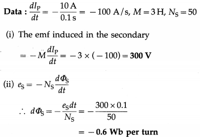
This gives the change in the magnetic flux per turn in the secondary.
Question 6.
The primary and secondary coils of a transformer, assumed to be ideal, have 20 and 300 turns of wire, respectively. If the primary voltage is VP = 10 sincot (in volt), what is the maximum voltage in the secondary coil?
Solution:
Data : NP = 20, NS = 300, VP = 10 sin ωt V
VS = \(\frac{N_{\mathrm{S}}}{N_{\mathrm{P}}}\) VP
= \(\frac{300}{20}\) × 10 sin ωt
= 150 sin ωt V
This is of the form V0 sin ωt, where V0 is the peak (or maximum) voltage.
∴ The maximum voltage in the secondary coil is 150 V.
Question 7.
A transformer converts 200 V ac to 50 V ac. The secondary has 50 turns and the load across it draws 300 mA current. Calculate (i) the number of turns in the primary (ii) the power consumed.
Solution:
Data: VP = 200 V, VS = 50 V, NS = 50, IS = 300mA = 0.3 A
(i) \(\frac{N_{\mathrm{P}}}{N_{\mathrm{S}}}=\frac{V_{\mathrm{P}}}{V_{\mathrm{S}}}\)
∴ The number of turns in the primary,
NP = NS\(\frac{V_{\mathrm{P}}}{V_{\mathrm{S}}}\)
= 50 × \(\frac{200}{50}\) = 200
(ii) Power consumed = VSIS = 50 × 0.3 = 15 W
Question 8.
A resistance of 3 Ω is connected to the secondary coil of 60 turns of an ideal transformer. Calculate the current (peak value) in the resistor if the primary has 1200 turns and is connected to 240 V (peak) ac supply. Assume that all the magnetic flux in the primary coil passes through the secondary coil and that there are no other losses.
Solution:
Data : R = 3 Ω, NS = 60, NP = 1200, VP = 240 V
VS = \(\frac{N_{\mathrm{S}}}{N_{\mathrm{P}}}\) × VP
= \(\frac{60}{1200}\) × 240 = 12 V (peak)
∴ The peak value of the current in the resistor in the transformer secondary coil is
IS = \(\frac{V_{\mathrm{S}}}{R}=\frac{12}{3}\) = 4 A
![]()
Question 9.
The primary of a transformer has 40 turns and works on 100 V and 100 W. Find the number of turns in the secondary to step up the voltage to 400 V. Also calculate the current in the secondary and primary.
Solution :
Data : NP = 40, VP = 100 V, PP = 100 W, VS = 400 V
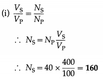
This gives the number of turns in the secondary coil.
(ii) Assuming PS = PS = 100 W,
VSIS = 100 W
∴ IS = \(\frac{100}{V_{\mathrm{S}}}=\frac{100}{400}\) = 0.25 A
This gives the current in the secondary coil.
(iii) VP . IP = PP ∴ IP = \(\frac{P_{\mathrm{P}}}{V_{\mathrm{P}}}=\frac{100}{100}\) = 1 A
This gives the current in the primary coil.
Question 10.
A transformer converts 400 volt ac to 100 volt ac The secondary of the transformer has 50 turns and the load across it draws a current of 600 mA. What is the current in the primary, the power consumed and the number of turns in the primary?
Solution:
Data : VP = 400 V. VS = 100 V, NS = 50, IS = 0.6 A
Assuming no power loss. PPVP = ISVS
∴ The current in the primary,
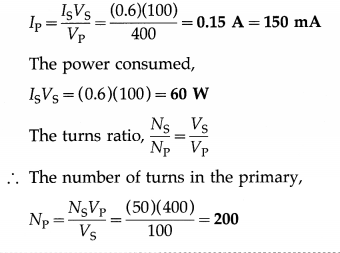
Question 11.
A step down transformer works on 220 V a mains. What is the efficiency of the transformer when a bulb of 100 Wf20 V is connected to the a mains and the current in the primary is 0.5 A ?
Solution:
Data: VP = 220V, VS = 20V, PS = 100W, IP = 0.5 A
The Input power. PP = IPVP = (0.5)220) = 110 W
The output power, PS = 100 W
∴ The efficiency of the transformer
= \(\frac{\text { output power }}{\text { input power }}=\frac{100}{110}\) = 0.9091 or 90.91%
Multiple Choice Questions
Question 1.
A circular loop is placed in a uniform magnetic field. The total number of magnetic field lines passing normally through the plane of the coil is called
(A) the displacement current
(B) the eddy current
(C) the self inductance
(D) the magnetic flux
Answer:
(D) the magnetic flux
Question 2.
According to Lenz’s law, the direction of the induced current in a closed conducting loop is such that the induced magnetic field attempts to
(A) maintain the original magnetic flux through the loop
(B) maximize the magnetic flux through the loop
(C) maintain the magnetic flux through the loop to zero
(D) minimize the magnetic flux through the loop.
Answer:
(A) maintain the original magnetic flux through the loop
Question 3.
A metallic conductor AB moves across a magnetic field as shown in the following figure.
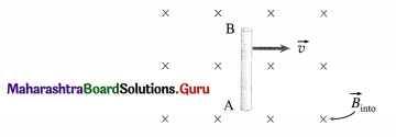
Which of the following statements is correct?
(A) The free electrons experience a magnetic force and move to the lower part of the conductor.
(B) The free electrons experience a magnetic force and move to the upper part of the conductor.
(C) The positive and negative charges experience a magnetic force and move, respectively, to the upper and lower parts of the conductor.
(D) The moving conductor gives rise to an emf but there is no separation of charges as they are bound in the solid structure.
Answer:
(A) The free electrons experience a magnetic force and move to the lower part of the conductor.
![]()
Question 4.
A bar magnet moves vertically down, approaching a circular conducting loop in the x-y plane. The direction of the induced current in the loop (looking down the z-axis) is
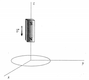
(A) anticlockwise
(B) clockwise
(C) alternating
(D) along negative z-axis.
Answer:
(A) anticlockwise
Question 5.
A moving conductor AB of length 1 makes a sliding electrical contacts at its ends with two parallel conducting rails. The rails are joined at the left edge (CD) by a resistance R to form a complete circuit.
The rate at which the magnetic flux through the area bounded by the circuit changes is
(A) Bv
(B) Bl/v
(C) Bvl
(D) Bv/l.
Answer:
(C) Bvl
Question 6.
A metre gauge train is heading north with speed 54 km/h in the Earth’s magnetic field 3 × 10⁻⁴ T. The emf induced across the axle joining the wheels is
(A) 0.45 mV
(B) 4.5 mV
(C) 45 mV
(D) 450 mV.
Answer:
(B) 4.5 mV
Question 7.
A conducting rod of length l rotates about one of its ends in a uniform magnetic field \(\vec{B}\) with a constant angular speed ω. If the plane of rotation is perpendicular to \(\vec{B}\), the emf induced between the ends of the rod is
(A) \(\frac{1}{2}\)Bωl2
(B) πl2Bω
(C) Bωl2
(D) 2Bωl2.
Answer:
(A) \(\frac{1}{2}\)Bωl2
Question 8.
A circular conducting loop of area 100 cm2 and resistance 3 Ω is placed in a magnetic field with its plane perpendicular to the field. If the field is spatially uniform but varies with time t (in second) as B(f) = 1.5 cos ωt tesla, the peak value of the current is
(A) 3 mA
(B) 5ω mA
(C) 300ω mA
(D) 500 mA.
Answer:
(B) 5ω mA
![]()
Question 9.
In a simple rectangular-loop ac generator, the time rate of change of magnetic flux is a maximum when
(A) the induced emf has a minimum value
(B) the plane of the coil is parallel to the magnetic field
(C) the plane of the coil is perpendicular to the magnetic field
(D) the emf varies sinusoidally with time.
Answer:
(B) the plane of the coil is parallel to the magnetic field
Question 10.
A simple generator has a 300 loop square coil of side 20 cm turning in a field of 0.7 T. How fast must it turn to produce a peak output of 210 V ?
(A) 25 rps
(B) 4 rps
(C) 2.5 rps
(D) 0.4 rps
Answer:
(B) 4 rps
Question 11.
A rectangular loop generator of 100 turns, each of area 1000 cm2, rotates in a uniform field of 0.02 π tesla with an angular velocity of 60 π rad/s. The maximum value of \(\frac{d \Phi_{\mathrm{m}}}{d t}\) is
(A) 12π V
(B) 12π2 Wb
(C) 6π2 V
(D) 12π2 V.
Answer:
(D) 12π2 V.
Question 12.
A 250 loop circular coil of area 16π2 cm2 rotates at 100 rev/s in a uniform magnetic field of 0.5 T. The rms voltage output of the generator is nearly
(A) 200\(\sqrt {2}\) V
(B) 20\(\sqrt {2}\) V
(C) 400 V
(D) 2\(\sqrt {2}\) MV.
Answer:
(A) 200\(\sqrt {2}\) V
Question 13.
Two tightly wound solenoids have the same length and circular cross-sectional area, but the wire of solenoid 1 is half as thick as solenoid 2. The ratio of their inductances is
(A) \(\frac{1}{4}\)
(B) \(\frac{1}{2}\)
(C) 2
(D) 4
Answer:
(D) 4
![]()
Question 14.
The wire of a tightly wound solenoid is unwound and used to make another tightly wound solenoid of twice the diameter. The inductance changes by a factor of
(A) 4
(B) 2
(C) \(\frac{1}{2}\)
(D) \(\frac{1}{4}\)
Answer:
(B) 2
Question 15.
The back emf of a dc motor is 108 V when it is connected to a 120 V line and reaches full speed against its normal load. What will be its back emf if a change in load causes the motor to run at half speed ?
(A) 66 V
(B) 12 V
(C) 60 V
(D) 54 V
Answer:
(D) 54 V
Question 16.
A single rectangular loop of wire, of dimensions 0.8 m × 0.4 m and resistance 0.2 Ω, is in a region of uniform magnetic field of 0.5 T in a plane perpendicular to the field. It is pulled along its length at a constant velocity of 5 m/s. Once one of its shorter side is just outside the field, the force required to pull the loop out of the field is
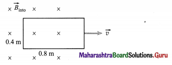
(A) 0.2 N
(B) 0.5 N
(C) 1 N
(D) 2 N.
Answer:
(C) 1 N
Question 17.
A pivoted bar with slots falls through a magnetic field. The bar falls the quickest if it is made of [Assume identical plate and slot dimensions. Ignore air resistance.]
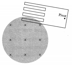
(A) copper
(B) a ferromagnetic
(C) aluminium
(D) plastic
Answer:
(D) plastic
Question 18.
Eddy currents are also called
(A) Maxwell currents
(B) Faraday currents
(C) displacement currents
(D) Foucault currents
Answer:
(D) Foucault currents
![]()
Question 19.
At a given instant the current and self-induced emf (e) in an inductor are directed as shown. If e = 60 V,
which of the following is true?

(A) The current is increasing at 2 A/s. 12 H
(B) The current is decreasing at 5 A/s.
(C) The current is increasing at 5 A/s.
(D) The current is decreasing at 6 A/s.
Answer:
(C) The current is increasing at 5 A/s.
Question 20.
A metal ring is placed in a region of uniform magnetic field such that the plane of the ring is perpendicular to the direction of the field. The field strength is increasing at a constant rate. Which of the following graphs best shows the variation with time t of the induced current I in the ring ?
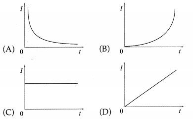
Answer:
(C)
Question 21.
At a given instant, the current through a 60 mH inductor is 50 mA and increasing at 100 mA/ s. The energy stored at that instant is
(A) 150 µJ
(B) 75 µJ
(C) 0.6 mJ
(D) 0.3 mJ
Answer:
(B) 75 µJ
Question 22.
The magnetic field within an air-cored solenoid is 0.8 T. If the solenoid is 40 cm long and 2 cm in diameter, the energy stored in its magnetic field is
(A) 32 J
(B) 3.2 J
(C) 6.4 kJ
(D) 64 kJ
Answer:
(A) 32 J
Question 23.
The adjacent graph shows the E induced emf against time of a coil rotated in a uniform magnetic field at a certain frequency. 0;
If the frequency of rotation is reduced to one half of its initial value, which one of the following graphs correctly shows the new variation of the induced emf with time.
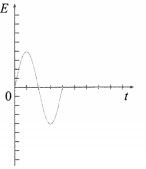
[All the graphs are drawn to the same scale.]
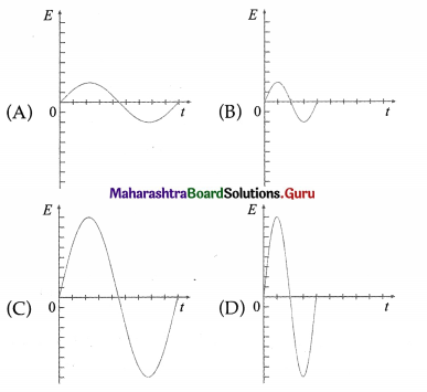
Answer:
(A)
Question 24.
A transformer has 320 turns primary coil and 120 turns secondary coil. Which of the following statements is true ?
(A) It changes current by a factor of \(\frac{8}{3}\) and is a step-up transformer.
(B) It is a step-down transformer and changes current by a factor of \(\frac{8}{3}\).
(C) It changes current by a factor of \(\frac{8}{3}\) and is a step-up transformer.
(D) It is a step-down transformer and changes current by a factor of \(\frac{8}{3}\).
Answer:
(B) It is a step-down transformer and changes current by a factor of \(\frac{8}{3}\).
![]()
Question 25.
Input power at 11000 V is fed to a step-down transformer which has 4000 turns in its primary winding. In order to get output power at 220 V, the number of turns in the secondary must be
(A) 20
(B) 80
(C) 400
(D) 800.
Answer:
(B) 80