Balbharti Maharashtra State Board 12th Physics Important Questions Chapter 9 Current Electricity Important Questions and Answers.
Maharashtra State Board 12th Physics Important Questions Chapter 9 Current Electricity
Question 1.
Define the following terms:
- Electrical circuit
- Junction
- Loop
- Branch
- Electrical network.
Answer:
- Electrical circuit: An electrical circuit, in general, consists of a number of electrical components such as an electrical cell, a plug key (or a switch), a resistor, a current meter (a milliammeter or an ammeter), a voltmeter, etc., connected together to form a conducting path.
- Junction: A point in an electrical circuit where two or more conductors are joined together is called a junction.
- Loop: A closed conducting path in an electrical network is called a loop or mesh.
- Branch: A branch is any part of an electrical network that lies between two junctions.
- Electrical network: An electrical network consists of a number of electrical components connected together to form a system of inter-related circuits.
Question 2.
State Kirchhoff’s first law or current law or junction law.
Answer:
The algebraic sum of the currents at a junction is zero in an electrical network, i.e. \(\sum_{i=1}^{n}\) Ii = 0, where Ii is
the current in the ith conductor at a junction having n conductors.
![]()
Question 3.
What is the sign convention used for Kirchhoff’s first law? Explain with an example.
Answer:
A current arriving at a junction is considered positive while a current leaving a junction is considered negative.
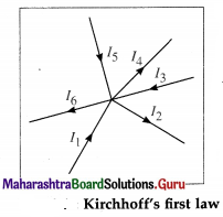
Consider a junction in a circuit where six current carrying conductors meet. Currents I1, I3 and I5 are considered positive as they arrive at the junction.
Currents I2, I4 and I6 are considered negative as they leave the junction.
Using Kirchhoff’s current law, \(\sum_{i=1}^{6}\) Ii = 0, we get,
I1 – I2 + I3 – I4 + I5 – I6 = 0
∴ I1 + I3 + I5 = I2 + I4 + I6
Thus the total current flowing towards the junction is equal to the total current flowing away from the junction.
[Note : As the current is the time rate of flow of charge, it follows that the net charge entering the junction in a given time equals the net charge leaving the junction in the same time. Thus, this law (current law/junction law) is based on the conservation of charge. ]
Question 4.
State Kirchhoff’s second law or voltage law or loop law.
Ans. The algebraic sum of the potential differences (products of current and resistance) and the electromotive forces (emf’s) in a closed loop is zero. Σ IR + Σ E = 0
Question 5.
What is the sign convention used for Kirchhoff’s second law ? Explain with an example.
Answer:
(1) While tracing a loop, if we traverse a resistor along the direction of conventional current, the potential difference across the resistor is considered negative. If we traverse the resistor opposite to the direction of conventional current, the potential difference across the resistor is considered positive.
(2) While tracing a loop within the source, if we travel from the negative terminal of the source (cell) to the positive terminal of the source (cell), the emf of the source (cell) is considered positive.
On the contrary, if we travel from the positive terminal of the source (cell) to the negative terminal of the source (cell), the emf of the source (cell) is considered negative.
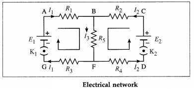
Consider the electrical network shown in above figure.
Tracing loop ABFGA in the clockwise direction, we get,
– I1R1 – I3R5 – I1R3 + E1 = 0
∴ E1 = I1R1 + I3R5 + I1R3
Tracing loop BFDCB in the anticlockwise direction, we get,
– I3R5 – I2R4 + E2 – I2R2 = 0
∴ E2 = I2R2 + I3R5 + I2R4
[Notes : (1) We may as well consider loop ABCDFGA and write the corresponding equation. (2) As the emf of a cell is the energy provided by the cell per unit charge in circulating the charge and the potential difference across a resistance is the work done per unit charge, it follows that this law (voltage law /loop law) is based on the conservation of energy.]
![]()
Question 6.
What is the basis of Kirchhoff’s current law and voltage law?
Answer:
Kirchhoff’s current law is consistent with the conservation of electric charge while the voltage law is consistent with the law of conservation of energy.
7. Solve the following
Question 1.
Determine the current flowing through the galvanometer shown in the figure below.
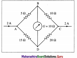
Solution:
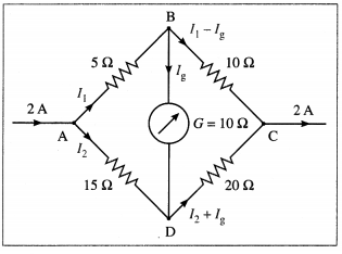
To find Ig we apply Kirchhoff’s voltage law.
Loop ABDA :
– 5I1 – 10Ig + 15I2 = 0
∴ – 5I1 + 15I2 = 10Ig
∴ -I1 + 3I2 = 2Ig ………….. (1)
Loop BCDB :
-10(I1 – Ig) + 20 (I2 + Ig) + 10Ig = 0
∴ – 10I1 + 10Ig + 20I2 + 20Ig + 10Ig = 0
∴ I1 – 2I2 = 4Ig …………. (2)
Adding Eqs. (1) and (2), we get, I2 = 6 Ig …………. (3)
Substituting for Z2 from Eq. (3) in Eq. (2).
∴ I1 = 12Ig + 4Ig = 16Ig
Now, I1 + I2 = 2 A by the data.
∴ 16Ig + 6Ig = 2A
∴ 22Ig = 2A
∴ Ig = \(\frac{2}{22}\) A = \(\frac{1}{11}\) A from B to D
This is the current flowing through the galvanometer.
Question 8.
State the factors on which the resistance Of a material depends.
Answer:
The resistance of a material depends upon tem-perature, strain, humidity, etc.
[Note : Depending upon the factors stated above, resistance may vary from near zero to thousands of megaohm.]
Question 9.
What are the applications of Wheatstone’s metre bridge?
Answer:
- Wheatstone’s metre bridge is used for measuring the values of very low resistance precisely.
- It can also be used to measure the quantities such as strain galvanometer, resistance, capacitance of a capacitor, inductance of an inductor, impedence of a combination of a resistor, capacitor and inductor and the internal resistance of a cell.
Question 10.
What is the balance point in Kelvin’s method to measure the resistance of a galvanometer?
Answer:
Kelvin’s method of determination of the galvanometer resistance is an equal deflection method. The balance point in Kelvin’s method is a point on the wire for which the bridge network is balanced and the galvanometer shows no change in deflection.
![]()
Question 11.
Why is Kelvin’s method to measure the resistance of a galvanometer called an equal deflection method?
Answer:
In Kelvin’s method of determination of the galvanometer resistance using a Wheatstone metre bridge, the galvanometer is connected in one gap of the bridge and a variable known resistance is connected in the other gap. The junction of the two gaps (say, B) is connected directly to a pencil jockey.
The jockey is tapped along the wire to locate the equipotential balance point D when the galvanometer shows no change in deflection.
Since the galvanometer shows the same deflection on making or breaking the contact between the jockey and the wire, the method is an equal deflection method.
12. Solve the following :
Question 1.
Four resistances 5 Ω, 10 Ω, 15 Ω and X (unknown) are connected in the cyclic order so as to form a Wheatstone network. Determine X if the network is balanced.
Solution:
Data : P = 5 Ω, Q = 10 Ω, R = 15 Ω
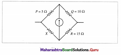
Since the network is balanced,
\(\frac{P}{Q}=\frac{X}{R}\)
∴ \(\frac{5}{10}=\frac{X}{15}\)
∴ X = 15 × \(\frac{5}{10}\) = 7.5 Ω
Question 2.
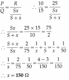
Resistances P = 10 Ω, Q = 15 Ω, S = 50 Ω and R = 25 Ω are connected in order in the arms AB, BC, CD and DA respectively of a Wheatstone network ABCD. A cell is connected between A and C. What resistance has to be connected in parallel to S to balance the network?
Solution:
Data : P = 10 Ω, Q = 15 Ω, S = 50 Ω and R = 25 Ω
Let x = resistance to be connected in parallel to S to balance the network. The resistance of the parallel combination of S and x is \(\frac{S x}{S+x}\) .
For the balanced network,
Question 3.
Four resistances 4 Ω, 8 Ω, X and 6 Ω are connected in the cyclic order so as to form Wheatstone’s network. If the network is balanced, find X.
Solution:
Data : P = 4Ω, Q = 8 Ω, R = X and S = 6 Ω
Since the network is balanced,
∴ \(\frac{P}{Q}=\frac{S}{R}\)
∴ X = 6\(\frac{8}{4}\) = 12 Ω
![]()
Question 4.
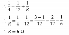
Four resistances 4 Ω, 4 Ω, 4 Ω and 12 Ω form a Wheatstone network. Find the resistance which connected across the 12 Ω resistance will balance the network.
Solution:
The resistance in each of the three arms of the network is 4 Ω. Hence, to balance the network, the resistance in the fourth arm must also be 4 Ω.
Hence, the resistance (R) to be connected across. i.e., in parallel to, the 12 Ω resistance should be such that their equivalent resistance is 4Ω.
Question 5.
Four resistances 80 Ω, 40 Ω, 10 Ω and 15 Ω are connected to form Wheatstone’s network ABCD as shown in the following figure.
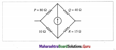
What resistance must be connected in the branch containing 10 Ω to balance the network?
Solution:
Data : P = 80 Ω, Q = 40 Ω, 10 Ω and R = 15 Ω are connected as shown in above figure.
When the network is balanced,
\(\frac{P}{Q}=\frac{S}{R}\)
∴ \(\frac{80}{40}=\frac{S}{15}\)
∴ S = 15 × 2 = 30 Ω
Let X be the resistance to be connected in series with 10 Ω, so as to obtain 30 Ω.
∴ X + 10 = 30
∴ X = 20 Ω
Question 6.
An unknown resistance is placed in the left gap and resistance of 50 ohms is placed in the right gap of a meter bridge. The null point is obtained at 40 cm from the left end. Determine the unknown resistance.
Solution:
Data : R =50 C in the right gap, lX =40 cm
\(\)
Now, lR = 100 – lX = 100 – 40 = 60 cm
∴ \(\frac{X}{50}=\frac{40}{60}\)
∴ X = 50 × \(\frac{2}{3}\) = \(\frac{100}{3}\) = 33.33 Ω
This is the unknown resistance.
Question 7.
Two resistances X and Y in the two gaps of a metre bridge give a null point dividing the wire in the ratio 2 : 3. If each resistance is increased by 30 Ω, the new null point divides the wire in the ratio 5 : 6, calculate each resistance.
Solution:
From the data, we have in the first case,
\(\frac{X}{Y}=\frac{l_{X}}{l_{Y}}=\frac{2}{3}\)
∴ 3X = 2Y ……….. (1)
and in the second case, \(\frac{X+30}{Y+30}=\frac{l_{X+30}}{l_{Y+30}}=\frac{5}{6}\)
∴ 6X + 180 = 5Y + 150
∴ 6X – 5Y = -30
∴ 6X = 5Y – 30
∴ 2(3X) = 5Y – 30 …………. (2)
Substituting the value of 3X from Eq. (1) in Eq. (2),
we get,
2(2Y) = 5Y – 30
∴ Y = 30 Ω
∴ X = \(\frac{2}{3}\)Y = 20 Ω
![]()
Question 8.
In a metre bridge experiment, with a resistance R1 in the left gap and a resistance X in the right gap, the null point is obtained at 40 cm from the left end of the wire. With a resistance R2 in the left gap and the same resistance X in the right gap, the null point is obtained at 50 cm from the left end of the wire. Where will be the null point if R1 and R2 are connected first in series and then in parallel in the left gap, the right gap still containing X?
Solution:
From the data in the example, we have:
When R1 is connected in the left gap and X in the right gap, lR1 = 40 cm, and with R2 in the left gap, lR2 50 cm.
∴ In the first case,
lX = 100 – lR1 = 100 – 40 = 60cm
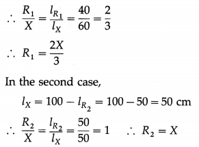
(i) When R1 and R2 are connected in series, the effective resistance is
RS = R1 + R2 = \(\frac{2 X}{3}\) + X = \(\frac{5 X}{3}\)
Let the corresponding null point be at a distance l1 from the left end of the wire.
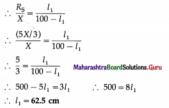
(ii) When R1 and R1 are connected in parallel, the effective resistance is
RP = \(\frac{R_{1} R_{2}}{R_{1}+R_{2}}=\frac{\frac{2 X}{3} \times X}{\frac{2 X}{3}+X}=\frac{2 X}{5}\)
Let the corresponding null point be at a distance l2 Erom the left end of the wire.
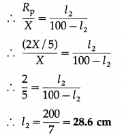
With the same resistance X in the right gap, the null points will be at 62.5 cm and 28.6 cm from the left end of the wire for the series and parallel combinations respectively of R1 and R2 in the left gap.
Question 9.
A uniform wire is cut into two pieces such that one piece is twice as long as the other. The two pieces are connected in parallel in the left gap of a metre bridge. When a resistance of 20 Ω is connected in the right gap, the null point is obtained at 60 cm from the right end of the bridge wire. Find the resistance of the wire before it was cut into two pieces.
Solution:
Let Rw be the resistance of the wire before it was cut into two pieces. Let L1, L2 and X1, X2 be the lengths and resistance of the two pieces.
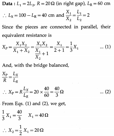
∴ The original resistance of the wire is
Rw = X1 + X2 = 40 + 20 = 60 Ω
Question 10.
Two resistances, 20 Ω and 30 Ω, are connected across the two gaps of a metre bridge as shown in the following figure.
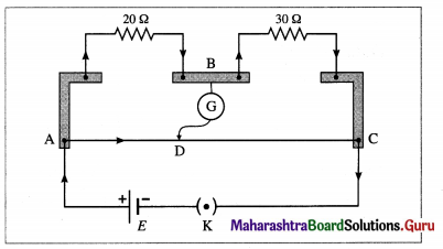
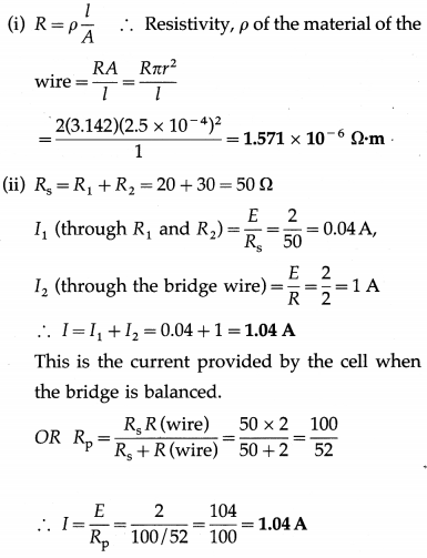
The bridge wire has diameter 0.5 mm and resistance 2 Ω. The emf of the cell is 2 V. Assume that the internal resistance of the cell is zero. Calculate (I) the resistivity (specific resistance) of the material of the bridge wire (ii) the current provided by the cell when the bridge is balanced.
Solution:
Data: R1 = 20 Ω, R2 = 30 Ω. Ig = 0, R (wire) = 2 Ω,
r (wire) = 0.25 mm = 2.5 x iO m (as the diameter of the wire is 0.5mm), l = 1 m, E = 2V
![]()
Question 11.
Two diametrically opposite points of a metal ring are connected to two tenninals of the left gap of a metre bridge. A resistance of 11 Ω is connected in the right gap. If the null point is obtained at 45 cm from the left end, find the resistance of the metal ring.
Solution:
Data: R = 11 Ω, LX = 45 cm
∴ LR = 100 – LX = 100 – 45 = 55cm
Let \(\frac{X}{2}\) be the resistance of each half of the metal ring. Therefore the resistance in the left gap is the effective resistance of the parallel combination of \(\frac{X}{2}\) and \(\frac{X}{2}\)
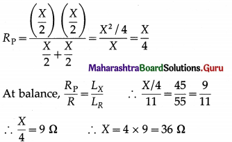
The resistance of the metal ring is 36 Ω
Question 12.
In a metre bridge experiment, the resistances R and X are connected in the left and right gap, respectively, and the null point is obtained at 33.7 cm from the left end. When a resistance of 12 Ω is connected in parallel to X, the null point is obtained at 51.9 cm from the left end. Calculate R and X.
Solution:
(1) In the first case,
lR = 33.7 cm, lX = 100 – 33.7 = 66.3 cm
∴ \(\frac{X}{R}=\frac{l_{X}}{l_{R}}=\frac{66.3}{33.7}\) …………….. (1)
(2) In the second case,
lR = 51.9 cm, lX = 100 – 51.9 = 48.1 cm
X’ = X || 12 Ω = \(\frac{12 X}{12+X}\)
∴ \(\frac{X^{\prime}}{R}=\frac{48.1}{51.9}\) ……………. (2)
Dividing Eq. (1) by Eq. (2), we get,
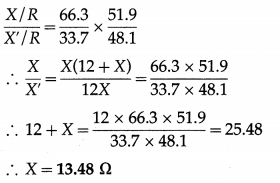
Then, from Eq. (1),
R = 13.48 × \(\frac{33.7}{66.3}\) = 6.852 Ω
Question 13.
What is the SI unit of potential gradient?
Answer:
The SI unit of potential gradient is the \(\frac{\text { volt }}{\text { metre }}\left(\frac{\mathrm{V}}{\mathrm{m}}\right)\).
Question 14.
Explain how two cells are connected so as to
(i) assist each other
(ii) oppose each other. Write the formulae for the corresponding effective emf.
Answer:
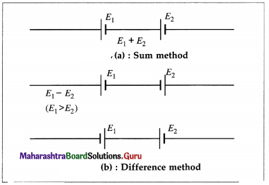
Consider two cells connected so that the positive terminal of the first cell is connected to the negative terminal of the second cell as shown in figure (a). The emf’s of the two cells are added up and the effective emf of the combination of the two cells is E1 + E2. This method of connecting two cells is called the sum method. Here, the cells assist each other.
Consider two cells connected so that their negative terminals are connected together or their positive terminals are connected together as shown in figure (b).
In this case their emf’s oppose each other and the effective emf of the combination of the two cells is E1 – E2(E1 > E2 assumed). This method of connecting two cells is called the difference method.
Question 15.
What is the internal resistance of the cell ?
Answer:
The internal resistance of a cell is the resistance offered by the electrolyte and electrodes in the cell.
![]()
Question 16.
Explain how a potentiometer is used as a voltage divider.
Answer:
A potentiometer can be used as a voltage divider to continuously change the output voltage of a voltage supply. As shown in the below figure, potential difference V is set up between points A and B of a potentiometer wire. One end of a device is connected to positive point A and the other other end is connected to a slider that can move along wire AB. The voltage V divides in proportion of lengths l1 and l2 as shown in figure.
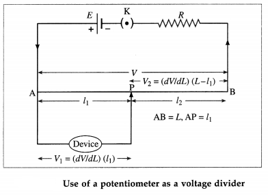
By using the slider we can change the output voltage from 0 to V.
Question 17.
State the precautions which must be taken in using a potentiometer.
Answer:
Precautions to be taken in using a potentiometer:
- The potential difference across the potentiometer wire must be greater than the emf or potential difference to be balanced. Hence, in comparing emfs, the driver emf E > E1, E2 (direct method) or E > E1 + E2 (combination method).
- The positive terminal of the cell with emf E1 and that with emf E2, or their combination, must be connected to the higher potential terminal of the potentiometer.
- The potentiometer wire must be of uniform cross section and homogeneous.
- The potentiometer wire should be long and have a high resistivity and low temperature coefficient of resistance.
Question 18.
State the advantages of a potentiometer over a voltmeter.
Answer:
Advantages of a potentiometer over a voltmeter :
(1) The cell, whose emf is being measured, draws no current from the circuit at the null point. Thus, the potentiometer measures the open-circuit potential difference across its terminals, or the emf E. A voltmeter will measure the terminal potential difference, V, of the cell in a closed circuit. This is because the resistance of a voltmeter is high but not infinite and hence the voltmeter is not ideal.
(2) By setting up a suitably small potential gradient along a long potentiometer wire, any small voltage can be measured. Increasing the length of the wire effectively decreases the potential gradient, and increases both the precision and accuracy of measurement.
(3) The adjustment of a potentiometer is a ‘null’ method which does not, in any way, depend on the calibration of the galvanometer. The galvanometer is used only to detect the current, not to measure it. The accuracy of a voltmeter is limited by its calibration.
(4) Since a potentiometer can measure both the emf and terminal potential difference of a cell, the internal resistance of the cell can be found.
19. Solve the following
Question 1.
In a potentiometer circuit. E = 2 V, r = 2 Ω, Rwire = 10 Ω, Rext = 1988 Ω and L = 4 m (in the usual notation). What is the potential gradient along the wire ?
Solution:

The potential gradient along the wire is 2.5 × 10⁻³ V/m
Question 2.
A potentiometer wire has length 2 m and resistance 10 Ω. It is connected in series with a resistance 990 Ω and a cell of emf 2 V. Calculate the potential gradient along the wire.
Solution:
Data : L 10 m, R = 10 Ω, Rext = 990 Ω, E =2 V
The current in the circuit is
I = \(\frac{E}{R+R_{\text {ext }}}=\frac{2}{10+990}=\frac{2}{1000}\) = 2 × 10⁻³ A
The potential difference across the wire is
V = IR = 2 × 10-3 × 10 = 2 × 10⁻² V
∴ The potential gradient along the wire
= \(\frac{V}{L}=\frac{2 \times 10^{-2}}{2}\) = 10-2 V/m
![]()
Question 3.
A potentiometer wire 4 m long has a resistance of 4 Ω. What resistance must be connected in series with the wire and a cell of emf 2 V having internal resistance of 2 Ω to get a potential drop of 10-3 V/cm along the wire?
Solution:
Data: L = 4 m, R = 4 Ω, E = 2 V, r = 2 Ω
The required potential drop per unit length of the wire is
10-4 V/cm = \(\frac{10^{-3} \mathrm{~V}}{10^{-2} \mathrm{~m}}\) = 0.1 V/m
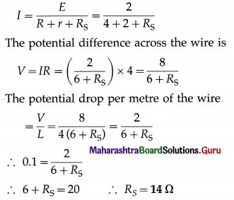
Let RS be the series resistance for which the desired potential drop is obtained.
The current in the circuit is
Question 4.
A potentiometer wire of length 5 m is connected to a battery. For a certain cell having negligible internal resistance, the null point is obtained at 250 cm. If the length of the potentiometer wire is increased by 1 m, where will be the new position of the null point?
Solution:
Data : L1 = 5m, L2 = 6m, l1 = 250 cm
E = (\(\frac{V}{L}\))l
where V/L is the potential gradient and l is the balancing length.
∴ E1= (\(\frac{V}{L_{1}}\))l1 = (\(\frac{V}{L_{2}}\))2
l2 = (\(\frac{L_{2}}{L_{1}}\)) × l1 = \(\frac{6}{5}\) × 250 = 300 cm
Question 5.
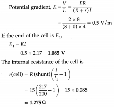
A potentiometer wire, of length 4 m and resistance 8 Ω, is connected in series with a battery of emf 2 V and negligible internal resistance. If the emf of the cell balances against a length of 217 cm of the potentiometer wire, find the emf of the cell. When the cell is shunted by a resistance of 15 Ω, the balancing length is reduced by 17 cm. Find the internal resistance of the cell.
Solution:
Data: L = 4 m, R = 8 Ω, E = 2V, r = 0,
R(shunt) = 15 Ω, l = 217 cm = 2.17 m,
l1 = 217 – 17 = 200 cm = 2 m
![]()
Question 6.
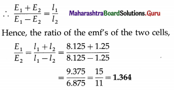
Two cells of emf’s E1 and E2 (E1 > E2) are connected in a potentiometer circuit so as to assist each other. The null point is obtained at 8.125 m from the high potential end of the potentiometer wire. When the cell with emf E2 is connected so as to oppose the emf E1, the null point is obtained at 1.25 m from the same end. Compare the emf’s of the two cells.
Solution:
Data : l1 = 8.125 m (cells assisting), l2 = 1.25 m (cells opposing)
E1 + E2 = Kl1 and E1 – E2 = Kl2
where K is the potential gradient.
Question 7.
A cell balances against a length of 200 cm on a potentiometer wire when it is shunted by a resistance of 8 Ω. The balancing length reduces by 40 cm when it is shunted by a resistance of 4 Ω. Calculate the balancing length when the cell is in an open circuit. Also calculate the internal resistance of the cell.
Solution:
Data : Part I : R = 8 Ω, l2 = 200 cm;
Part II : R = 4 Ω, l2 = 160 cm
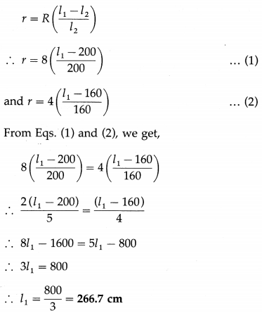
This is the balancing length when the cell is in open circuit. The internal resistance of the cell,
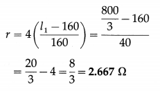
Question 8.
When a resistance of 12 Ω is connected across a cell, its terminal potential difference is balanced by 120 cm of a potentiometer wire. When a resistance of 18 Ω is connected across the same cell, the balancing length is 150 cm. Find the balancing length when the cell is in open circuit. Also calculate the internal resistance of the cell.
Solution:
Data : Part I : R = 12 Ω, l2 = 120 cm;
Part II : R = 18 Ω, l2 = 150 cm
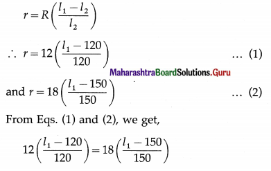
∴ \(\frac{l_{1}-120}{10}=\frac{6\left(l_{1}-150\right)}{50}\)
∴ 5 (l1 – 120) = 6(l1 -150)
∴ 5l1 – 600 = 6l1 – 900
∴ l1 = 300 cm
This is the balancing length when the cell is in open circuit.
∴ r = \(12\left(\frac{l_{1}-120}{120}\right)=\frac{300-120}{10}=\frac{180}{10}\) = 18 Ω
This is the internal resistance of the cell a unit
![]()
Question 20.
What is a galvanometer?
Answer:
A galvanometer is a device used to detect weak electric currents in a circuit. The current may be of the order of a few microamperes, or even a few nanoamperes.
Question 21.
State the principle of working of a moving coil galvanometer.
Answer:
A current-carrying coil suspended in a magnetic field experiences a torque which rotates the plane of the coil and tends to maximize the magnetic flux through the coil. The torque due to the spring or the suspension fibre to which the coil is attached tends to restore the coil to its initial position. In equilibrium, the coil comes to rest and its deflection is proportional to the current through the coil.
Question 22.
Explain the basic construction of a galvanometer.
Answer:
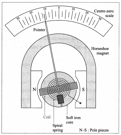
A galvanometer consists of a coil of a large number of turns of fine insulated copper wire wound on a rectangular nonconducting, nonmagnetic frame. The coil is pivoted (or suspended) between cylindrically concave pole pieces of a horseshoe strong permanent magnet. The coil swings freely around a cylindrical soft iron core fitted between the pole pieces. The deflection of the coil can be read with a pointer attached to it. The position of the pointer on the scale provided depends on the current passing through the galvanometer (or the potential difference across it). A galvanometer can be used as an ammeter or a voltmeter with a suitable modification.
[Note : A table galvanometer has a resistance of about 50 Ω and can carry a current up to about 1 mA.]
Question 23.
What are the modifications necessary to convert a moving-coil galvanometer (MCG) into an ammeter?
Answer:
To convert a moving-coil galvanometer (MCG) into an ammeter, the following modifications are necessary :
- The effective current capacity of the MCG must be increased to a desired higher value.
- A galvanometer when connected in series with a resistance, should not decrease the current through the resistance. Hence, the effective resistance of the galvanometer must be decreased by connecting an appropriate low resistance across it. An ideal ammeter should have zero resistance.
- It must be protected from the damages which are likely to occur due to the passage of an excess electric current.
Question 24.
State the function of the shunt in modifying a galvonometer to an ammeter.
Answer:
Functions of the shunt:
- It lowers the effective resistance of the ammeter
- It is used to divert to a large part of total current by providing an alternate path and thus it protects the instrument from damage.
- With a shunt of proper value, a galvanometer can be modified into an ammeter of practically any desired range.
![]()
Question 25.
Explain how a moving-coil galvanometer is converted into an ammeter. Derive the necessary formula.
Answer:
A moving-coil galvanometer is converted into an ammeter by reducing its effective resistance by connecting a low resistance S across the coil. Such a parallel low resistance is called a shunt since it shunts a part of the current around the coil, shown in below figure. That makes it possible to increase the range of currents over which the meter is useful.
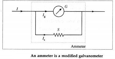
Let I be the maximum current to be measured and Ig the current for which the galvanometer of resistance G shows a full-scale deflection. Then, the shunt resistance S should be such that the remaining current I – Ig = Is is shunted through it.
In the parallel combination, the potential difference across the galvanometer = the potential difference across the shunt
∴ Ig G = Is S
= (I – Ig)S
∴ S = (\(\frac{I_{\mathrm{g}}}{I-I_{\mathrm{g}}}\)) C
This is the required resistance of the shunt. The scale of the galvanometer is then calibrated so as to read the current in ampere or its submultiples (mA. µA) directly.
[Notes :
(1) Thick bars of manganin are used for shunts because manganin has a very small temperature coefficient of resistivity.
(2) The fraction of the current passing through the galvanometer and shunt are, respectively,
\(\frac{I_{g}}{I}=\frac{S}{S+G}\) and \(\frac{I_{g}}{I}=\frac{G}{S+G}\)
(3) On the right hand side of Eq. (1), dividing both the numerator and denominator by Ig, we get,
S = \(\frac{1}{\left(I / I_{\mathrm{g}}\right)-1}\) ∙ G = \(\frac{G}{p-1}\)
where p = I/Ig is the range-multiplying factor, i.e., the current range of the galvanometer can be increased by a factor p by connecting a shunt whose resistance is smaller than the galvanometer resistance by a factor p – 1.
∴ p = \(\frac{G+S}{S}\)
If RA is the resistance of the ammeter,
RA = \(\frac{G S}{G+S}=\frac{G}{p}\)]
Question 26.
How do you calculate the shunt required to increase the range p times?
Answer:
The value of shunt resistance required to convert a galvanometer into an ammeter is given by,
S = (\(\frac{I_{\mathrm{g}}}{I-I_{\mathrm{g}}}\)) G
If the current I is p times the current Ig, then I = pIg. Using this in the above expression, we get,
S = \(\frac{G I_{\mathrm{g}}}{p I_{\mathrm{g}}-I_{\mathrm{g}}}\) OR S = \(\frac{G}{p-1}\)
This is the required shunt resistance to increase the range p times.
![]()
Question 27.
What is the current flowing through the shunt resistance?
Answer:
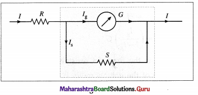
If IS is the current through the shunt resistance, then the remaining current (I – IS) will flow through the galvanometer.
Now, the potential difference across the galvanometer = the potential difference across the shunt
∴ G(I – IS) = S IS
∴ GI – GIS = S IS
∴ SIS + GIS = G I
∴ IS = (\(\frac{G}{S+G}\))I
This is the current flowing through the shunt resistance.
Question 28.
What are the modifications required to convert a moving-coil galvanometer into a voltmeter?
Answer:
The modifications required to convert a moving- coil galvanometer into a voltmeter are as follows :
- The effective resistance of the galvanometer should be very high. This is because a voltmeter requires a very small current to deflect its pointer. If a larger current than this flows through the voltmeter, the voltmeter is said to load the circuit and it will record a much smaller voltage drop.
- The voltage measuring capacity (range) should be increased to a desired value.
- It must be protected from damages which are likely to occur due to an excess applied potential difference.
Question 29.
Explain how a moving-coil galvanometer is converted into a voltmeter. Derive the necessary formula.
Answer:
A moving-coil galvanometer is converted into a voltmeter by increasing its effective resistance by connecting a high resistance Rs in series with the galvanometer, shown in figure. The series resistance is also useful for changing the range of any given voltmeter.
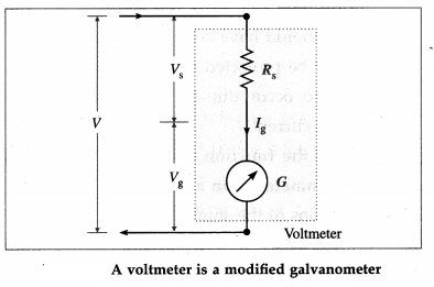
Let G be the resistance of the galvanometer coil and Ig the current required for a full-scale deflection.
Let V be the maximum potential difference to be measured. The value of the series resistance RS should be such that when the potential difference applied across the instrument is V, the current through the galvanometer is Ig.
In the series combination, the potential difference V gets divided across the galvanometer (resistance, G) and the resistance RS :
V = IgG + IgRS = Ig(G + RS)
∴ RS = \(\frac{V}{I_{\mathrm{g}}}\) – G
This is the required value of the series resistance. The scale of the galvanometer is then calibrated so as to read the potential difference in volt or its submultiples, e.g., mV, directly.
[Notes :
(1) A series multiplier is made of manganin wire because manganin has a very small temperature coefficient of resistivity.
(2) The maximum potential difference Vg that can be dropped across the galvanometer is Vg = Ig G. Therefore, the above expression for the series resistance may be rewritten as
Rs = \(\frac{V G}{I_{\mathrm{g}} G}\) – G
= \(\frac{V G}{V_{\mathrm{g}}}\) – G = G(p – 1)
where p = V/Vg is the range-multiplying factor, i.e., the voltage range of the galvanometer can be increased by a factor of p by connecting a series resistance which is (p – 1) times the galvanometer resistance.
∴ p = \(\frac{V}{V_{g}}=\frac{\left(R_{\mathrm{S}}+G\right) I_{\mathrm{g}}}{G I_{\mathrm{g}}}=\frac{R_{\mathrm{S}}+G}{G}\)
Since the resistance of the voltmeter is Rv = RS + G,
p = \(\frac{R_{\mathrm{V}}}{G}\)
∴Rv = Gp]
![]()
Question 30.
State the functions of the series resistance in modifying a galvanometer into a voltmeter.
Answer:
Functions of the series, resistance:
- It increases the effective resistance of the voltmeter.
- It drops off a larger fraction of the measured potential difference thus protecting the sensitive meter movement of the basic galvanometer.
- With resistance of proper value, a galvanometer can be modified to a voltmeter of desired range. .
Question 31.
Distinguish between an ammeter and a voltmeter
Answer:
Ammeter | Voltmeter |
| 1. It measures current. | 1. It measures potential difference. |
| 2. It is connected in series with a resistance. | 2. It is connected in parallel to a resistance. |
| 3. An ammeter should have very low resistance (ideally zero). | 3. A voltmeter should have very high resistance (ideally infinite). |
| 4. Its range can be increased by decreasing the value of shunt resistance. | 4. Its range can be increased by increasing the value of series resistance. |
| 5. The resistance of an ammeter is RA = | 5. The resistance of a voltmeter is Rv = G + Rs = Gp. |
32. Solve the following
Question 1.
Calculate the value of the shunt which when connected across a galvanometer of resistance 38 Ω will allow 1/20th of the current to pass through the galvanometer.
Solution:
Data : G = 38 Ω, Ig / I = \(\frac{1}{20}\)
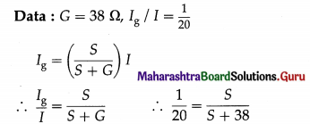
∴ S + 38 = 20 S
∴ 19 S = 38
∴ S = 2 Ω
This is the required value of the shunt.
Question 2.
A galvanometer is shunted by 1/r of its resistance. Find the fraction of the total current passing through the galvanometer.
Solution:
Let G be the resistance of the galvanometer, I the total current and Ig the current through the galvanometer when it is shunted. The resistance of the shunt is
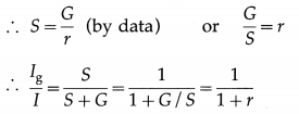
The fraction \(\frac{1}{1+r}\) of the total current passes through the galvanometer.
[Note : The fraction of the current through the shunt = \(\frac{I_{\mathrm{S}}}{I}=1-\frac{I_{\mathrm{g}}}{I}=\frac{r}{1+r}\)]
Question 3.
A resistance of 3 Ω is connected in parallel to a galvanometer of resistance 297 Ω. Find the fraction of the current passing through the galvanometer.
Solution:
Data : G = 297 Ω, S = 3 Ω
Ig = \(\frac{S}{S+G}\) ∙ I
∴ \(\frac{I_{\mathrm{g}}}{I}=\frac{S}{S+G}=\frac{3}{3+297}=\frac{3}{300}\) = 0.01
This is the fraction of the current through the galvanometer.
[Note: The fraction of the current through the shunt
= \(\frac{I_{\mathrm{S}}}{I}\) = 1 – 0.01 = 0.99]
![]()
Question 4.
The combined resistance of a galvanometer of resistance 1000Ωand its shunt is 25 Ω. Calculate the value of the shunt.
Solution:
Data: G = 1000 Ω, RA =25 Ω
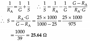
This is the value of the shunt.
Question 5.
A galvanometer with a coil of resistance 40 Ω gives a full scale deflection for a current of 5 mA. How will you convert it into an ammeter of range 0 – 5 A?
Solution:
Data: G = 40 Ω, Ig = 5 mA = 5 × 10⁻³ A, I = 5 A
To convert a galvanometer into an ammeter, a shunt (i.e., low resistance in parallel) should be connected with the galvanometer coil. The required shunt resistance,
S = (\(\frac{I_{\mathrm{g}}}{I-I_{\mathrm{g}}}\)) G = (\(\frac{5 \times 10^{-3}}{5-5 \times 10^{-3}}\)) × 40
= \(\frac{200}{4995}\) = 0.04 Ω
Question 6.
A galvanometer has a resistance of 16 Ω and gives a full scale deflection when a current of 20 mA is passed through it. The only shunt resistance available is 0.04 Ω which is not sufficient to convert the galvanometer to an ammeter to measure up to 10 A. What resistance should be connected in series with the coil of the galvanometer so that the range of the ammeter is 10 A ?
Solution:
Data: G =16 Ω, Ig = 20 mA = 0.02 A,
S = 0.04 Ω, I = 10 A
Let X be the resistance to be connected in series with the coil of the galvanometer.
The fraction of the current through the galvanometer is \(\frac{I_{\mathrm{g}}}{I}\).

\(\frac{I_{\mathrm{g}}}{I}=\frac{S}{(G+X)+S}\)
∴ (G + X) + S = \(\frac{I}{I_{\mathrm{g}}}\) × S = \(\frac{10}{0.02}\) × 0.04 = 20
∴ X = 20 – (16 + 0.04) = 3.96 Ω
Alternate method:
Let G’ = G + X = 16 + X
The range multiplying factor,
p = \(\frac{I}{I_{\mathrm{g}}}=\frac{10}{0.02}\) = 500
Then, S = \(\frac{G^{\prime}}{p-1}\)
∴ G’= 16 + X = S(p – 1)
= 0.04(500 – 1) = 19.96 Ω
∴ X = 19.96 – 16 = 3.96 Ω
Question 7.
A galvanometer of resistance 100 C gives a full scale deflection for a current of 2 mA. How will you use it to measure (i) current up to 2 A (ii) voltage up to 10 V?
Solution:
Data : G = 100 Ω, Ig = 2 mA = 2 × 10⁻³ A, I = 2 A, V = 10 V
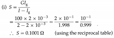
A resistance of 0.1001 Ωshould be connected in parallel to the coil of the galvanometer to measure current up to 2 A.
(ii) Rs = \(\frac{V}{I_{\mathrm{g}}}\) – G
= \(\frac{10}{2 \times 10^{-3}}\) – 100 = 5000 – 100 = 4900 Ω
A resistance of 4900 Ω should be connected in series with the coil of the galvanometer to measure voltage up to 10 V.
![]()
Question 8.
Calculate the value of resistance needed to convert a moving-coil galvanometer of 60 Ω which gives a full scale deflection for a current of 50 mA into (i) an ammeter of range 0 – 5 A (ii) a voltmeter of range 0 – 50 V.
Solution:
Data : G = 60 Ω, Ig = 50 mA = 5 × 10⁻² A, I = 5 A, V = 50 V
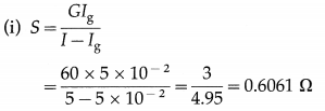
A resistance of 0.6061 Ω should be connected in parallel to the coil of the galvanometer to measure current up to 5 A.
(ii) Rs = \(\frac{V}{I_{\mathrm{g}}}\) – G
= \(\frac{50}{5 \times 10^{-2}}\) – 60
= 1000 – 60 = 940 Ω
A resistance of 940 Ω should be connected in series with the coil of the galvanometer to measure voltage up to 50 V.
Question 9.
A voltmeter of resistance 500 Ω can measure a maximum voltage of 5 V. How can it be made to measure a maximum voltage of 100 V? Solution:
Data : G = 500 Ω, Vg = 5 V, V = 100 V
To increase the range of the voltmeter by a factor p = \(\frac{V}{V_{\mathrm{g}}}\), a resistance R should be connected in series with it.
Rs = G(p – 1) = 500(\(\frac{100}{5}\) – 1) = 9500 Ω
Question 10.
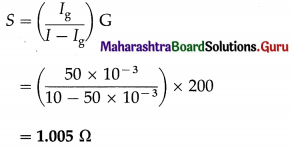
A moving-coil galvanometer of resistance 200 ohms gives a full scale deflection of 100 divisions for a current of 50 milliamperes. How will you convert it into an ammeter to read 2 amperes for 20 divisions?
Solution:
Data : G = 200 Ω, Ig = 50 mA = 50 × 10-3 A
The total number of scale divisions is 100. The ammeter has to read 20 divisions for a current of 2 A. Hence, for 100 divisions, the current must be I = 10 A.
To convert the galvanometer into an ammeter, a shunt must be connected in parallel to the galvanometer coil. The required shunt resistance,
Question 11.
A galvanometer of resistance 50 Ω has a current sensitivity of 5 div/mA. The instrument has 25 divisions. How will you convert it into a voltmeter of range 0 – 50 V ?
Solution:
Data : G = 50 Ω, V = 50 V
For a current of 1 mA, the galvanometer shows a deflection of 5 divisions. Hence, for a full scale deflection (i.e. deflection of 25 divisions), the current passing through the galvanometer should be 5 mA.
∴ Ig = 5mA = 5 × 10⁻³ A
To convert the galvanometer into a voltmeter, a high resistance must be connected in series with the galvanometer coil. This series multiplier,
Rs = \(\frac{V}{I_{\mathrm{g}}}\) – G = \(\frac{50}{5 \times 10^{-3}}\) – 50
= 9950 Ω
Multiple Choice Questions
Question 1.
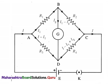
For a Wheatstone network shown in the following figure, Ig = 0 when .
(A) E = 0
(B)VB = VD
(C) VB > VD
(D) VB < VD
Answer:
(B)VB = VD
Question 2.
A potentiometer wire is 100 cm long and a constant potential difference is maintained across it. Two cells are connected in series, first to support one another and then in opposite direction. The balance points are obtained at 50 cm and 10 cm from the positive end of the wire in the two cases. The ratio of emfs is
(A) 5 : 4
(B) 3 : 4
(C) 3 : 2
(D) 5 : 1
Answer:
(C) 3 : 2
Question 3.
When the current in a potentiometer wire decreases, the potential gradient
(A) decreases
(B) increases
(C) remains the same provided the resistance and the length of the wire remain the same
(D) remains the same, irrespective of the resistance . of the wire and its length.
Answer:
(A) decreases
![]()
Question 4.
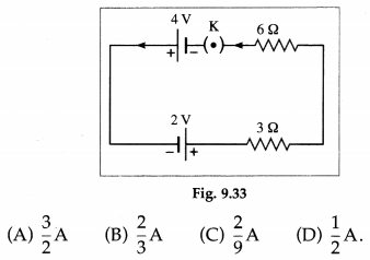
In the circuit given below the current through the 6 Ω resistor will be
Answer:
(B) \(\frac{2}{3}\) A
Question 5.
The accuracy of a potentiometer wire can be increased by
(A) increasing its length
(B) decreasing its length
(C) using a cell of higher emf
(D) using a cell of lower emf.
Answer:
(A) increasing its length
Question 6.
A cell of emf 1.1 V and internal resistance r is connected across an external resistor of resistance R = 10 r. The potential difference across the resistor is
(A) 0.1 V
(B) 0.9 V
(C) 1.0 V
(D) 1.1 V.
Answer:
(C) 1.0 V
Question 7.
When a metal conductor connected in the left gap of a metre bridge is heated, the null point
(A) will shift towards right
(B) will shift towards left
(C) will remain unchanged
(D) will shift towards right or left depending upon the resistivity of the metal.
Answer:
(A) will shift towards right
Question 8.
In using a Wheatstone’s bridge to accurately measure an unknown resistance, a calibrated known variable resistor is varied until
(A) the change in the galvanometer reading is zero
(B) a change in the value of the variable resistor produces no change in the galvanometer reading
(C) the potential difference across the unknown resistance is zero
(D) the potential difference across the galvanometer is zero.
Answer:
(D) the potential difference across the galvanometer is zero.
![]()
Question 9.
In a Wheatstone network, the resistances in cyclic order are P = 10 Ω, Q = 5 Ω, S = 4 Ω and R = 4 Ω. Then, for the bridge to balance,
(A) 5 Ω should be connected in parallel to Q = 5 Ω
(B) 10 Ω should be connected in series with Q = 5 Ω
(C) 5 Ω should be connected in series with P = 10 Ω
(D) 10 Ω should be connected in parallel to P = 10 Ω
Answer:
(D) 10 Ω should be connected in parallel to P = 10 Ω
Question 10.
Two resistors, R1 and R, are connected in the left gap and the right gap of a metre bridge, and the balancing length is obtained at 20 cm from the left. On inter-changing the resistors in the two gaps, the balancing length shifts by
(A) 20 cm
(B) 40 cm
(C) 60 cm
(D) 80 cm.
Answer:
(C) 60 cm
Question 11.
An instrument which can measure terminal potential difference as well as electromotive force (emf) is
(A) Wheatstone’s metre bridge
(B) a voltmeter
(C) a potentiometer
(D) a galvanometer
Answer:
(C) a potentiometer
Question 12.
A 10 m long wire of resistance 2012 is connected in series with a resistance of 10 Ω and a battery of emf 3 V and negligible internal resistance. The potential gradient, in µV / mm, along the wire is
(A) 2
(B) 20
(C) 200
(D) 2000
Answer:
(C) 200
Question 13.
A 10 m long potentiometer wire has a resistance of 20 Ω. If it is connected in series with a resistance of 55 Ω and a cell of emf 4 V and internal resistance 5 Ω, the potential gradient along the wire is
(A) 0.1 V/m
(B) 0.08 V/m
(C) 0.01 V/m
(D) none of these.
Answer:
(A) 0.1 V/m
Question 14.
A potential gradient of 6 × 10⁻³ V/ mm is set up on a potentiometer wire which has a resistance of 2 Ω/m. Two emfs 2.5 V and 1.3 V, once assisting and then opposing each other, are balanced on the wire. The balancing lengths in the two cases are in the ratio
(A) 19 : 2
(B) 19 : 6
(C) 25 : 13
(D) 2:1.
Answer:
(B) 19 : 6
![]()
Question 15.
A potentiometer wire, having a resistance of 5 Ω and length 10 m, is connected in series a cell of emf 5 V and an external resistance of 495 Ω. A potential difference of 1.5 mV will balance against a length of
(A) 3 cm
(B) 30 cm
(C) 3 m
(D) none of these.
Answer:
(B) 30 cm
Question 16.
A load resistance R is connected across a cell of emf E and internal resistance r. If the closed-circuit p.d. across the terminals of the cell is V, the internal resistance of the cell is
(A) (E – V) R
(B) (V – E)R
(C) \(\frac{E-V}{V} R\)
(D) \(\frac{E-V}{V}\)
Answer:
(C) \(\frac{E-V}{V} R\)
Question 17.
The open-circuit potential difference across the terminals of a cell balances on 150 cm of a potentiometer wire. When the cell is shunted by a 4.9 Ω resistor, the balancing length reduces to 147 cm. The internal resistance of the cell is
(A) 0.01 Ω
(B) 0.05 Ω
(C) 0.1 Ω
(D) 1 Ω
Answer:
(C) 0.1 Ω
Question 18.
To convert a galvanometer into an ammeter
(A) a high resistance is connected in parallel to the galvanometer
(B) a high resistance is connected in series with the galvanometer
(C) a low resistance is connected in parallel to the galvanometer
(D) a low resistance value is connected in series with the galvanometer.
Answer:
(C) a low resistance is connected in parallel to the galvanometer
Question 19.
To convert a galvanometer into a voltmeter
(A) a high resistance is connected in parallel to the galvanometer
(B) a high resistance is connected in series with the galvanometer
(C) a low resistance is connected in parallel to the galvonometer
(D) a low resistance is connected in series with the galvonometer.
Answer:
(B) a high resistance is connected in series with the galvanometer
Question 20.
An ideal ammeter has
(A) a moderate resistance
(B) a high resistance
(C) an infinite resistance
(D) zero resistance
Answer:
(D) zero resistance
Question 21.
An ideal voltmeter has
(A) a low resistance
(B) a high resistance
(C) an infinite resistance
(D) zero resistance
Answer:
(C) an infinite resistance
![]()
Question 22.
The fraction of the total current passing through the galvanometer is
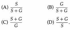
Answer:
(A) \(\frac{S}{S+G}\)